
Installation Instructions


TPS
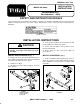
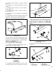
Assemble new 90_ fitting to T-fitting as shown in
figure 15.
Assemble hose to 90_ fitting with clamp as shown
in figure 15.
Assemble female coupler to hose with clamp as
shown in figure 15.
Assemble coupler plug to female coupler as
shown in figure 15.
Secure hose to side of tank frame assembly with
(3) cable ties.
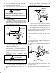
Using dimensions shown in figure 16, locate, mark
and drill (3) .250" dia. holes in left tank skid flange.
.3% Holes may already be in tank skid flange.
)'41%
42( ,.4-3 #+)/
Insert a push mount clip into each drilled hole. Clip
opening to be positioned away from tank. Clips will be
used to secure control box harness to tank skid flange.
)'
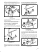
& -.3 %04)//%$ 5)3( ! 2/1!6%1 /4,/
Assemble 90° fitting, reducing nipple and to
suction strainer as shown in figure 17.
)'41%
4#3).- 231!)-%1
_ )33)-'
%$4#)-' -)//+%
!+% #.4/+%1
Using dimensions shown in figure 18, locate, mark
and drill (2) .266" dia. holes in left frame rail of vehicle.
)'41%
$)!
Mount suction strainer assembly and strainer strap
to frame rail with (2) 1/4-20 x 1-1/2" lg. capscrews,
flat washers and lock nuts (Fig. 19). !*% 241%
24#3).- 231!)-%1 )2 /.2)3).-%$ 2. !11.5 /.)-32
&.15!1$
)'41%
4#3).- 231!)-%1 !22%,"+6
31!)-%1 #+!,/
Assemble hose to 90_ fitting with clamp as shown
in figure 20.
)'41%
.2%
%,!+% #.4/+%1
.4/+%1 /+4'
!+% #.4/+%1
!-* .43+%3 (.2%
!-* .43+%3 (.2% #.4/+%1