Form No. 3378-458 Rev A PrecisionSense™ PS6000 Turf Assessment Trailer Model No. 09900—Serial No. 313000001 and Up g022036 Register at www.Toro.com.
which signals a hazard that may cause serious injury or death if you do not follow the recommended precautions. WARNING CALIFORNIA Proposition 65 Warning Figure 2 This product contains a chemical or chemicals known to the State of California to cause cancer, birth defects, or reproductive harm. 1. Safety alert symbol This manual uses 2 other words to highlight information. Important calls attention to special mechanical information and Note emphasizes general information worthy of special attention.
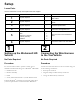
Contents Safety Introduction .................................................................. 2 Safety ........................................................................... 3 Safe Operating Practices........................................... 3 Safety and Instructional Decals ................................. 4 Setup ............................................................................ 6 1 Setting up the Workman® HD Vehicle .....................
• • If the tow vehicle engine stalls or the machine loses any loose nuts, bolts, and screws to ensure that the machine is in safe operating condition. Check that safety switches and shields are attached and functioning properly. Do not operate unless they are functioning properly. • Operation • Never operate the assessment trailer when it is not • • • • • • • connected to a tow vehicle. Be alert, slow down, and use caution when making turns. Look behind and to the side before changing directions.
120–8294 1. Warning—read the Operator’s Manual. 3. Entanglement hazard, chain—keep away from moving parts; keep all guards and shields in place. 2. Warning—keep bystanders away from the machine. 120–8278 1. Stored energy hazard—1) Stop the machine; 2) Move the machine forward and allow the weight to rotate downward; 3) Ensure the weight is rotated downward before servicing.
Setup Loose Parts Use the chart below to verify that all parts have been shipped. Procedure Description Use Qty. 1 No parts required – Setup the Workman® HD vehicle and foam marker. 2 3 4 No parts required – Connect the wire harness to the tow vehicle. No parts required – Install the spectrometers. No parts required – Remove the tine-alignment tool. 5 Assessment trailer Hitch Bolt (3/8 x 3 inches) Locknut (3/8 inch) Cable tie 1 1 2 2 6 Mount the hitch to the assessment trailer.
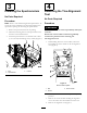
3 4 Installing the Spectrometers Removing the Tine-Alignment Tool No Parts Required No Parts Required Procedure Procedure Note: There is a left-hand and right-hand spectrometer. To ensure the correct installation, the mounting brackets have specific hole spacings for mounting the spectrometers. WARNING 1. Remove the spectrometers from the packing. The sensor holder can rotate up suddenly and injure someone. 2. Match the mounting holes in each spectrometer with the holes in the machine frame.
5. Store the alignment tool and the hardware in the tool box. 1 2 Figure 6 g022221 3. Hitch tube 1. Bolt (3/8 x 3 inches) Figure 5 2. Locknut (3/8 inch) 1. Sensor holder 2. Tine-alignment tool 4. Route the wire harness along the right side of the hitch tube (Figure 7). 5 5. Plug the harness clips into the holes in the side of the hitch tube. 6. Install the cable ties into the harness clips and secure the harness with cable ties (Figure 7).
Note: This trailer uses a ball socket that requires a 2 inch ball for the hitch. 1. Back the tow vehicle up to the assessment trailer. 2. Adjust the ball socket to the same level as tow vehicle hitch as follows: A. Set the hitch on a jack stand to keep the trailer parallel to the ground (Figure 8). Figure 10 1. Hitch tube 2. Coupler lever, locked position 2 1 g022325 Figure 8 1. Jack stand 2. Frame is parallel to the ground B.
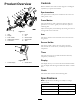
Controls Product Overview 9 Become familiar with all the controls (Figure 11 and Figure 12) before you operate the machine. 10 Spectrometers The spectrometers analyze the condition of the turf as the trailer passes over it. Foam Marker The foam marker is used to mark the path the tailer has passed over. Use this to guide you for the next path for collecting data. Adjust the frequency the foam drops by turning the valve on the right side of the foam tank. Figure 11 1. Hitch 2. Display 6. Clutch 7.
Operation • Turn off the clutch, that drives the rotating arm, when turning the vehicle at the end of a sampling pass or when stopping for any reason. Note: Determine the left and right sides of the machine from the normal operating position. • Turn off the , that drives the rotating arm, when crossing paved or gravel surfaces. Think Safety First • Check for bent or broken tines after hitting something Carefully read all of the safety instructions and decals in the safety section.
Note: It is critical to start and end at the same spot, without overlapping the start and end points (Figure 14). Data collection can start at any point along the Perimeter of the area. Collect the perimeters of all individual sample areas at once, or one at a time, just before the area is sampled. 1 2 3 4 5 3 g022124 Figure 13 Initial Screen 1. Copy data button 4. Information button 2. Log data button 5. Options button 1 3. Base map button 7.
Note: When you reach the green while defining a fairway, make a rounded turn in front of the green (Figure 14). Continue to log perimeter data while turning in front of the green. 7. When finishing the perimeter, stop the vehicle 3.1 to 3.7 m (10 to 12 ft) before the starting point. 8. Press the Stop button. Note: It is critical to start and end at the same spot, without overlapping the start and end points. Leaving a short gap between the start and stop points is acceptable. 9. Remove the irrigation flag.
1 2 3 4 Figure 17 Sports Field 1. Perimeter of sample area 3. Data collection path 2. Sample area 4. 3.1 to 4.
4 3 1 2 1 2 3 g023069 Figure 19 Log Data Screen 1. Back button 3. Foam on button—turns on the foam marker 2. Log on button—turn on to log data g023283 4. If prompted, measure the soil temperature with the soil thermometer by doing the following: A. Insert the soil thermometer into the soil (5.08 cm) 2 inches. Figure 18 Golf Fairway 1. Start 3. 3.1 to 4.6 m (10 to 15 ft) between passes 2. Data collection path 4. Perimeter of sample area B.
1 2 3 4 5 Figure 21 g022130 Figure 20 Log Temperature Screen 1. Add the tens digits 4. Subtract the ones digits 2. Subtract the tens digits 5. Save button 1. Log off button 3. Clutch on button 2. Foam on button Downloading and Copying Data 3. Add the ones digits 1. Insert a USB flash/thumb drive into the USB port inside control box on trailer (Figure 35). 6. Shift Workman vehicle into low range and 1st gear. 2. Press the Copy Data button from main display screen (Figure 13). 7.
Exiting During Sample Data Collection If you need to pause during the sample data collection process due to golfers or other reasons, do the following: 1. Turn the clutch off and stop the machine. 2. Once stopped, insert an irrigation flag into the turf or leave a pile of foam. 3. Turn the foam marker off 4. Drive to a safe location. 5. To resume the sample data collection, return to where you left collecting data. 6. Remove the flag. 7.
2. Select the Sprinkler button from the Base Map menu (Figure 15). 3. Press the Start button to begin collecting sprinkler head location data (Figure 23). 4. The display will show the progress of the collection and indicate when it is complete. 1 2 g022137 Figure 24 1. Back button 2. Start button Collecting Point Data 1 2 g022136 Use this function to collect a distinct point that is not a sprinkler head, such as a drain inlet or a valve box. Figure 23 1. Back button 2. Start button 1.
Taking Digital Photos Using the Options Screen Note: When taking photos, it is recommended to use a camera with GSNN (GPS) capability. Follow the instructions with the camera for best results. Use this function to change measurement units or to access demo or help features. • Units—allows you to switch between metric and U.S. units for entering soil temperature (Figure 27).
Using the Turf Holder lubricating oils, grease, or other petroleum products to the compressor motor assembly. Use the turf holder to prevent dirt and debris from collecting on the tines. Use the turf holder when turf conditions consistently leave soil on the tines or the tines lift the turf after sampling. 1. Slide the tines through the foot of the turf holder (Figure 29). 2. Install the turf holder to the sensor holder with 2 bolts (3/8 x 1-1/4 inches) (Figure 29). 1.
Using a Ramp to Load the Machine Important: This machine is not for road use. Do not exceed 32 km/h (20 mph) when towing the machine. Transport the machine on a flatbed when the speed will exceed 32 km/h (20 mph). Use extreme caution when loading units on trailers or trucks. One full width ramp that is wide enough to extend beyond the rear tires is recommended instead of individual ramps for each side of the unit (Figure 31).
Demo—the function or screen in the operator interface display accessed from the Options screen. Allows the user to demonstrate the system without actually logging the results. Sprinkler—the function within the Base Map function in the operator interface used to record GNSS (GPS) location points for individual sprinkler heads. Display—the function or screen in the operator interface display accessed from the Options screen. Allows the user to demonstrate the system without actually logging the results.
Maintenance Note: Determine the left and right sides of the machine from the normal operating position. Recommended Maintenance Schedule(s) Maintenance Service Interval Maintenance Procedure After the first 50 hours • Adjust the drive chains. Before each use or daily After each use Every 100 hours Before storage Yearly • Check the tire pressure. • Check the tines. • Clean the spectrometer lenses. • Clean the trailer. • Grease the trailer. • Paint chipped surfaces.
Electrical System Maintenance Drive System Maintenance Servicing the Fuses Adjusting the Drive Chains The electrical system is protected by fuses. It requires no maintenance. If a fuse blows, check the component or circuit for a malfunction or short. Service Interval: After the first 50 hours Yearly 1. Loosen the nut for the arm-chain idler pulley (Figure 36). 1. Stop the machine. 2. Open the control box. 2. Push the nut towards the arm and tighten the nut. This removes any slack in the chain. 3.
Maintaining the Sensor Checking the Tines Service Interval: Before each use or daily Check the tines for the following: • Before each use, check and ensure the soil tines are not loose, bent, broken, worn, or excessively covered with rust. • Ensure the soil tines are perpendicular to the frame of the trailer. If the tines are not perpendicular; refer to Aligning the Tines (page 26). Replacing the Tines Note: Do not over tighten the tines.
1 2 g022060 Figure 40 1. Sensor holder 1. Loosen the alignment bolts under the rotating pivot (Figure 41). Figure 39 1. Sensor holder 4. Lower plastic block 2. Upper plastic block 5. Metal plate 3. Tine 6. Bolt 2. Misaligned tines Important: Do not totally remove the bolts. Aligning the Tines WARNING The sensor holder can rotate up suddenly and injure someone. Ensure the sensor holder is held and gradually rotated into position when removing the tine-alignment tool.
1 2 4. Rotate the sensor holder down to ensure that the square plastic block will fit into the square opening in the tine-alignment tool (Figure 43). 1 5. If needed, position the tine-alignment tool to allow the plastic block to fit into the square opening in the tine-alignment tool. 1 3 2 g022017 3 5 g023286 Figure 43 Figure 41 1. Side bolts 2. Center bolt 4 1. Sensor holder 2. Left rear of the frame 3. Sensor holder 4. Bolts and nuts 5. Plastic block in the tine-alignment tool 3.
10. Measure the distance between the frame and the left edge of the tine-alignment tool, and write that dimension on the tine-alignment tool. 11. Remove the tine-alignment tool from the machine frame (Figure 42). 12. Place the tine-alignment tool and hardware into the tool box. 1 2 3 g022019 Figure 44 Top view 1. Bolt (3/8 x 1 inch) 3. Sensor holder 2. Sensor 1 2 3 g022020 Figure 45 Bottom view 1. Plastic block in the tine-alignment tool 3. Tine 2. Nut (3/8 inch) 8.
Cleaning Storage Cleaning the Trailer Cleaning and Storage 1. Clean the foam marker as follows: Service Interval: After each use—Clean the trailer. A. Position the machine on a level surface, stop the pump, set the parking brake, stop the engine, and remove the ignition key. Before each use or daily—Clean the spectrometer lenses. Important: You can wash the trailer with mild detergent and water. Do not pressure wash the trailer. Avoid excessive use of water, especially near the drive system.
Troubleshooting Problem Possible Cause Corrective Action 1. Verify that the vehicle is outside with a clear view of the sky. 1. Move the vehicle and trailer to an open area. 2. The GNSS (GPS) antena is not aquiring a signal. 2. Check the GNSS (GPS) lights on the back side of the white GNSS (GPS) antenna.
Schematics (Rev.