
Operator's Manual


5.Storethealignmenttoolandthehardwareinthetool
box.
g022221
2
1
Figure5
1.Sensorholder
2.Tine-alignmenttool
5
MountingtheHitchtothe
AssessmentTrailer
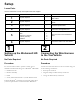
Partsneededforthisprocedure:
1Assessmenttrailer
1Hitch
2
Bolt(3/8x3inches)
2
Locknut(3/8inch)
6
Cabletie
Procedure
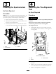
1.Positiontheassessmenttraileronaat,levelsurface.
2.Insertthehitchtubeintotheframebrackets(Figure6).
3.Securethetubetotheframewith2bolts(3/8x3
inches)and2locknuts(3/8inch)(Figure6).
Figure6
1.Bolt(3/8x3inches)
3.Hitchtube
2.Locknut(3/8inch)
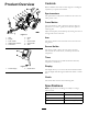
4.Routethewireharnessalongtherightsideofthehitch
tube(Figure7).
5.Plugtheharnessclipsintotheholesinthesideofthe
hitchtube.
6.Installthecabletiesintotheharnessclipsandsecure
theharnesswithcableties(
Figure7).
Figure7
1.Wireharness3.Hitchtube
2.Cabletie
4.Harnessclip
6
ConnectingtheTrailertothe
TowVehicle
NoPartsRequired
Procedure
Important:Ensurethattheballsocketisadjustedto
keepthetrailerparalleltotheground.
8