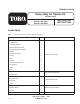
FORM NO. 3323-792 Heavy Duty Air Cleaner Kit for Out Front Z Part No. 100–2402 Part No. 100–2403 Part No. 100–2404 INSTALLATION INSTRUCTIONS Loose Parts Note: Use the chart below to identify parts for assembly. DESCRIPTION QTY.
Installation Instructions DESCRIPTION QTY. USE Air Cleaner Bracket 1 Hex Head Screw 2 Nuts 2 Air Cleaner 1 Hex Head Screw 2 Nuts 2 Radiator Clamp 2 Install Hoses to Air Cleaner Filter Finder Kit 1 Install Filter Finder Kit Filter Guard 1 Cover Plate 1 Screws 3 Nuts 3 Wing Nut 2 Carriage bolts 2 This kit contains a heavy–duty air cleaner, carburetor, hose adapter, hoses and mounting hardware.
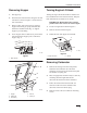
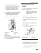
Installation Instructions Removing Hopper Turning Engine Lift Hook 1. Tilt hopper up. 2. Disconnect the wire harnesses along the rear left side frame as shown in figure 1. Ensure that it is free of the frame. Turning the engine lift hook will allow clearance for hose installed later in this instruction sheet. Keep the hook and hardware for future use if needed. 3. Remove safety clip from end of gas spring to hopper. Disconnect gas spring from ball stud attached to machine frame (Fig. 2).
Installation Instructions 5. Lift and pivot the carburetor to unhook the choke link, throttle link, and throttle dampening spring attached to the carburetor. Discard the old carburetor. 6. Check the equipment throttle and choke controls for proper operation. Be sure the plates in the carburetor are opening and closing fully with the movement of the control levers. 6. Remove the carburetor gasket from the intake manifold and clean off any remaining material using an aerosol gasket remover. 7.
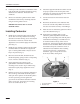
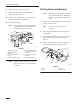
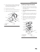
Installation Instructions 11. Position the new adapter plate over the carburetor gasket and pull the breather tube through the corresponding hole until the plate is seated between the flanges. The end of the breather hose must point into the carburetor throat. Install the three mounting screws removed in step 1 and torque them to 9.9 NSm (88 in. lb) (Fig. 5). 12.
Installation Instructions Drilling Holes into Bumper 8. Mark center of 3–1/2” hole. (Fig. 7). 9. Remove bolt that was used when locating template position (Fig. 7). Note: 10. Using 3–1/2I diameter hole saw, cut a hole at the specified area in template (Fig. 7). 1. 11. Reinstall bolt. (Fig. 7). Note: Part of hole will be cut through metal support. Remove any burrs from the metal support after hole is cut. 2 Template 3 must be used to locate the proper location for holes.
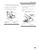
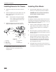
Installation Instructions 5. Rotate the leftside of bumper up to gain access to drill holes on front leftside of bumper (Fig. 9). 6. Drill two 11/32” holes onto the front of bumper (Fig. 9). Remove template. 7. Reinstall the bumper to machine frame. Installing Air Cleaner Bracket 1. Align holes in bracket with holes drilled in the left front of bumper. 2. Install 5/16I bolts into holes and tighten (Fig. 10). Note: Install bolts with heads towards the rear of the machine.
Installation Instructions Installing Air Cleaner 3 IMPORTANT: There are two types of bumpers. Figure 11 shows the extended bumper. Figure 12 shows the recessed bumper. 1 Refer to #1 in figures 11 and 12 to determine which type of bumper you have. 4 IMPORTANT: Ensure you install bolts in the correct holes in bracket. 1. 1 TOP VIEW 5 2 Install bolts in the correct holes for which type of bumper you have. Install bolts with heads towards the top (Fig. 11 or 12). m-4577 Figure 12 2.
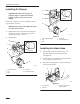
Installation Instructions 4. Locate position for R–clamp by measuring down 6” from top of tube and centered on tube. Mark center of hole in R–clamp (Fig. 14). 5. Drill a 9/32” hole into the tube. 6. Install R–clamp around air intake hose (Fig. 14). 7. Install screw into R–clamp and tube (Fig. 14). Installing Flange Connector 1. Install a hose clamp onto end of air intake hose. Insert flange connector in to intake hose. Tighten hose clamp (Fig. 15). 2.
Installation Instructions Installing Hoses to Air Cleaner Installing Filter Minder 1. Install hose clamps on to the ends of the two hoses. 1. 2. Install the adapter hose and air intake hose onto the air cleaner canister and tighten the hose clamps (Fig. 16). Note: 3. IMPORTANT: Do not discard instructions. Save for future reference and use. Using Filter Minder Ensure that air inlet points straight down. Adjust by loosening bracket screw. Tighten bracket screw when adjustment is done.
Installation Instructions Test System Installing Filter Guard 1. Reconnect the spark plug leads. Check the engine oil level. 1. Hold guard up to the bumper so the bottom edge of hole in guard lines up with the bottom edge of bumper (Fig. 18). Clamp to bumper. 2. Perform the final carburetor adjustments as follows. 2. Using the guard as a template, drill three 11/32I holes into bumper (Fig. 18). 3. Install two 5/16” screws into outside holes (Fig. 18).
Installation Instructions Servicing the Air Cleaner 1 3 4 Primary Filter: Clean or replace every 200 operating hours. Safety Filter: Replace after every 600 operating hours. Note: 5 Service the air cleaner more frequently if operating conditions are extremely dusty or sandy. 2 m–4387 1 Figure 19 Removing the Filter 1. Disengage the power take off (PTO), set the parking brake, and turn the ignition key to “OFF” to stop the engine. Remove the key. Remove spark plug wire(s) and remove the key. 2.
Installation Instructions Template #1 Fold Line 3I DIA. Hole Do Not cut out this circle in paper template.
Installation Instructions 14
Installation Instructions Template #2 Align with metal support edge. 3–1/2I DIA. Hole Do Not cut out circle in paper template.
Installation Instructions 16
Installation Instructions Template #3 Align to edge of bumper Fold Line Do Not cut out these circles in paper template.
Installation Instructions 18
Installation Instructions 19
Installation Instructions 20