
Installation Instructions

Installation Instructions
5
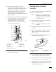
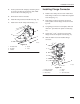
11. Position the new adapter plate over the
carburetor gasket and pull the breather tube
through the corresponding hole until the plate is
seated between the flanges. The end of the
breather hose must point into the carburetor
throat. Install the three mounting screws
removed in step 1 and torque them to 9.9 NSm
(88 in. lb) (Fig. 5).
12. Position the adapter gasket and air intake adapter
onto the adapter plate, so the hose connection
neck is facing straight back in the engine
compartment. Secure with the seven M6
thread–forming screws. Torque the screws to
10.7 NSm (95 in.–lb.) (Fig. 5).
2
3
7
M-4571
1
3
4
5
6
8
9
Figure 5
1. Triangular
Plugs
2.
Plug Screws
3.
Carburetor gasket
4. Carburetor
5.
Air Cleaner Base Gasket
6.
Adapter Plate
7.
Adapter Gasket
8.
Air Intake Adapter
9. Screws
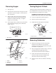
13. Place rag or tape over air intake adapter opening
to prevent debris entering.
Cutting
Holes in Plastic
Console
A 3I and 3–1/2I diameter hole saw is needed to drill
into the left side plastic console.
Note: Templates 1 and 2 must be used to
locate the correct location for holes.
Templates are located in the back of
this instruction sheet.
1. Locate and cut out templates 1 and 2 from the
back of this instruction sheet.
Note: Do not cut out large circles in paper
templates.
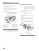
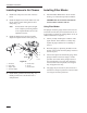
2. Take template number one and fold it across the
fold line.
3. Place template number one onto the top of the
plastic console as shown in figure 6. Tape to
plastic console.
4. Using 3I diameter hole saw, cut a hole at the
specified area in template (Fig. 6).
1
2
3
4
m-4573
Figure 6
1. Template
#1 (Folded)
2. T
emplate Position on
console
3. 3”
Diameter Hole to be cut
4.
Leftside console
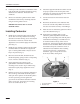
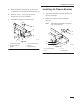
5. Locate template number two and cut out small
hole. Fold template at the specified fold lines.
6. Place small cut out hole onto bolt head and place
the fold in the bend of metal support. (Fig. 7).
7. Align diagonal line on template with the edge of
metal support. Tape template to plastic console
and metal support (Fig. 7).