
Installation Instructions

Installation Instructions
6
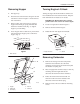
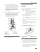
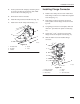
8. Mark center of 3–1/2” hole. (Fig. 7).
9. Remove bolt that was used when locating
template position (Fig. 7).
10. Using 3–1/2I diameter hole saw, cut a hole at
the specified area in template (Fig. 7).
11. Reinstall bolt. (Fig. 7).
Note: Part of hole will be cut through metal
support. Remove any burrs from the
metal support after hole is cut.
4
m-457
9
1
7
3
6
5
2
Figure 7
1. Template
#2 (Folded)
2. T
emplate Position on
console
3.
3–1/2” Diameter Hole to
be cut
4. Bottom
of Leftside console
5. Bolt
Head (Remove bolt
after 3–1/2” hole location
is marked.)
6.
Cut out circle (Align onto
bolt head)
7.
Edge of Metal Support
Note: Figure 7 shows machine as if it were
tipped on its side. Do not tip machine
on its side.
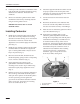
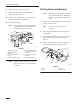
Drilling
Holes into Bumper
Note: Template 3 must be used to locate the
proper location for holes. Template 3 is
located in the back of this instruction
sheet.
1. Locate and cut out template three from the back
of this instruction sheet.
Note: Do not cut out circles in paper
template.
2. Take template number three and fold it across
the fold line.
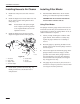
3. Place template number three onto the top of the
rear bumper as shown in figure 9. Tape to
bumper.
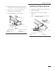
4. Remove the three bolts as shown in figure 8.
Loosen the fourth bolt but do not remove.
1
2
m-4580
3
4
Figure 8
1. Bolts
2. Nuts
3. Bumper
4. Bolt
(Loosen)