
Installation Instructions

Installation Instructions
9
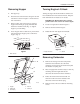
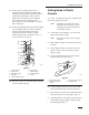
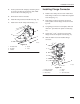
4. Locate position for R–clamp by measuring down
6” from top of tube and centered on tube. Mark
center of hole in R–clamp (Fig. 14).
5. Drill a 9/32” hole into the tube.
6. Install R–clamp around air intake hose (Fig. 14).
7. Install screw into R–clamp and tube (Fig. 14).
3
2
5
1
4
Figure 14
1. Air
Intake Hose
2. R–Clamp
3.
6 inches
4. Screw
5. Tube
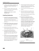
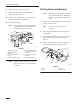
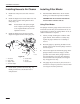
Installing
Flange Connector
1. Install a hose clamp onto end of air intake hose.
Insert flange connector in to intake hose. Tighten
hose clamp (Fig. 15).
2. Insert flange connector and hose into the top
hole in plastic. Center flange connector into the
top hole.
3. Using flange connector as a template, mark and
drill 3/32I pilot holes into plastic console (Fig.
15).
4. Screw 5/16I x 3/4I (19 mm) screws into the
flange connector and plastic console (Fig. 15).
5. Slide air intake hood onto installed flange
connector.
2
1
4
3
7
65
Figure 15
1. Flange
Connector
2.
Air Intake Hood
3.
Hose Clamp
4. Screw
5. Hose
6.
3/32” Pilot Holes