
Operator's Manual


G006238
1
2
3
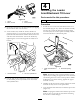
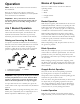
Figure19
1.Loaderarm/attachment
lever
3.Relayharness
2.Connector
4.Connecttheplugcomingfromnewlevertotheplug
connectorintherelaywireharness.
5.Securetherelayharnessconduittotheupper
hydraulicpipe,forwardofthespoolvalve,witha
suitablecabletie.
Important:Securetherelayharnessbacktothe
hydraulicpipesoastoensuretheharnessand
wiringdoesnotinterferewiththeoperationof
theparkingbrakeleverand/thebrakeswitch.
6.Installtherighthandpanelassemblybyloweringit
overthenewloaderarm/attachmenttiltleverand
feedtheparkingbrakeleverthroughit.
7.Installthefourscrewsremovedpreviouslytosecure
therighthandpanelassemblytothecontrolpanel
assembly(Figure6).
8.Installtherighthandrearcoversupportandsecure
ittothemachineusingthethreescrewsremoved
previously(Figure5).
5
InstallingtheValveManifold
SolenoidHarness
Partsneededforthisprocedure:
1
Valvemanifoldsolenoidharness
Procedure
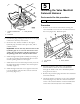
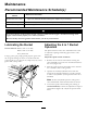
1.Removethesixscrewsandwasherssecuringthe
valvemanifoldcovertothe4in1bucketandremove
thecover(Figure20).Retainallparts.
G006239
1
2
3
Figure20
1.4in1Bucket
3.Screw,washer
2.Cover
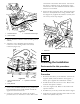
2.Feedtheconnectorendofthevalvemanifold
solenoidharnessfromthevalvemanifoldside
throughtheinsideofthevalvemanifoldhydraulic
hoseprotectivesleeve.
3.Removetheprotectiveplugsfromthevalvemanifold
solenoidterminals.
4.Attachtheharnessconnectorstothevalvemanifold
solenoids(Figure21)withtheconnectormarked‘L’
ontheoutersolenoidandtheconnectormarked‘R’
ontheinnersolenoid(closesttothemanifold).
12