
Operator's Manual


G006246
12
L
R
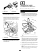
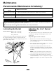
Figure28
1.Speedcontrolknob2.Speedcontrollockingnut
•Toincreasetheopening/closingspeedofthe
bucket,turntheknobclockwise.
•Todecreasetheopening/closingspeedofthe
bucket,turntheknobcounterclockwise.
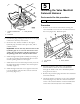
5.Withtheenginestillrunning,operatetheauxiliary
hydraulicslevertotheforwardowposition.Refer
tothetractionunitOperator’sManual.
6.Presstherockerswitchontheloaderarm/attachment
tiltleverandobservethespeedofthe4in1bucket
jawsopeningandclosing.
7.Operatetheauxiliaryhydraulicsleverfromthe
neutraltoforwarddirectionacoupleoftimesto
relieveanyhydraulicsystempressureinthevalve
manifold.
8.Iffurtheradjustmentisrequired,repeatinstructions
inStep4.
9.Whentheadjustmenthasbeencompleted,turnthe
speedcontrollockingnutclockwisetosecurethe
setting.
10.Lowertheloaderarmandswitchofftheengine.
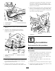
11.Installthevalvemanifoldcovertothe4in1
bucketandsecurewiththesixscrewsandwashers
(Figure20).Tightenthescrewssecurely.
Important:The4in1Bucketmustnotbeused
withoutthevalvemanifoldcoverinstalledand
securedinplace.Thewarrantyonthevalve
manifoldassemblywillbevoidedifthecoveris
notinstalled,orincorrectlyinstalled.
Storage
1.Beforelongtermstorage,washtheattachmentwith
milddetergentandwatertoremovedirtandgrime.
2.Checkandtightenallbolts,nutsandscrews.Repair
orreplaceanypartthatisdamagedorworn.
3.Ensurethatallthehydraulichosecouplersare
connectedtogethertopreventcontamination
enteringthehydraulicsystem.
4.Paintallscratchedorbaremetalsurfaces.Paintis
availablefromyourAuthorizedServiceDealer.
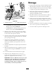
5.Usingagreasegun,pumpgeneralpurposegrease
intothesixpivotpointgreasenipplesonthebucket
untilthegreasebeginstoexudefromthepivot
bearings.
6.Storetheattachmentinaclean,drygarageorstorage
area.Coverittoprotectitandkeepitclean.
7.Coverthebuckettoprotectitandkeepitclean.
20