
Operator's Manual


2
RemovingtheLoader
Arm/AttachmentTiltLever
NoPartsRequired
Procedure
Theloaderarmsmaylowerwhenintheraised
positioncrushinganyoneunderthem.
Installthecylinderlockbeforeperforming
maintenancethatrequiresraisedloaderarms.
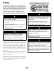
1.Raisetheloaderarmsandinstallthecylinder
safetylock.Removethehairpincotterandclevis
pinsecuringthecylinderlocktotheloaderarm
(Figure4).
G004182
3
2
1
Figure4
1.Cylinderlock3.Clevispin
2.Liftcylinder
4.Hairpincotter
2.Lowerthecylinderlockoverthecylinderrodand
secureitwiththeclevispinandhairpincotter
(Figure4).
3.Slowlylowertheloaderarmsuntilcylinderlock
contactsthecylinderbodyandrodend.
4.Switchofftheengine,removethekeyfromthekey
switchandallowtheenginetocool.
5.Openandremovetherearaccesscover.Refertothe
tractionunitOperator’sManual.
6.Loosenthebatterynegative(–)cableterminalnut,
andremovethecableterminalfromthebatterypost.
Retainallparts.
7.Opentheenginehoodandsecureintheopen
positionwiththeproprod.Refertothetractionunit
Operator’sManual.
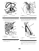
8.Removethethreescrewssecuringtherighthand
rearcoversupportassemblytothecontrolpaneland
theloadertowerassemblies(Figure5),Removethe
cover.
G006225
2
1
Figure5
1.Righthand,rearcover
2.Screw
9.Removethefourscrewssecuringtherighthand
panelassemblytothecontrolpanelassembly
(Figure6).
G006226
3
3
2
1
Figure6
1.Righthandpanel
3.Screw
2.Controlpanelassembly
7