
Operator's Manual


10.Removetherighthandpanelassemblybyliftingit
overtheloaderarm/attachmenttiltleverandfeedit
fromtheparkingbrakelever.
Note:Onemostmodels,removingtherighthand
panelreleasestheparkingbrakeleverandtheparking
brakeswillbeapplied.
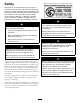
11.Loosenthelocknutatthebaseoftheloaderarm/
attachmenttiltlever(Figure8).Unscrewandremove
theleverfromthespoolvalve.
G006227
2
1
Figure7
1.Loaderarm/attachmenttilt
lever,existing
2.Locknut
3
InstallingtheRelayHarness
Partsneededforthisprocedure:
1Relayharness
2
Self-tappingscrews(#12[5mm])
1Boxconnector
1Harnessbracket
Procedure
1.Ifaheatshieldisinstalledtoprotecttheelectrical
componentsunderthedash,removethefasteners
securingtheshieldandremovetheshieldbefore
proceeding.Retainallfasteners.
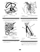
2.Disconnectthemainwiringharnessfromthe
followingdashcomponentstoallowroomforthe
4in1bucketwiringtobeinstalled:thefuelgauge,
hydraulicoiltemperature,hourmeter/tachometer
(Figure8).
Disconnectenoughcomponentstoallowthewiring
harnesstoberoutedbehindthekillandstartrelays.
G006228
1
2
3
4
5
Figure8
1.Dashcomponents,Interior4.Headlightpowersource,
mainwiringharness
2.Mainwiringharness,
existing
5.Existingkillandstart
relays
3.Openingintheframe
3.Locatetherightandleftrelaysattheendofthe
wiringharness(Figure9).Removetherelaysfrom
8