
Operator's Manual


therelaybrackettoexposethemountingholesinthe
relaybracket.Retainallparts.
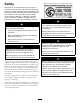
Figure9
1.Relayend
2.Loaderarm/attachmentleverconnector
3.Powerconnector,toheadlightconnectorinmainharness
4.Fourprongs,shownloose
4.Securetheharnesstotheinteriorofthedash:
G006229
1
2
3
4
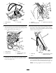
Figure10
1.Relayharness3.Drillhere
2.Relaybracketend
4.Selftappingscrew
A.Positiontherelaybracketendoftheharness
insidethedashasshownin(Figure10)andmark
thetwoopeningsinthebracket.
B.Removetherelaybracketandharnessandverify
thetwomarksarevisible.
C.Drilltwopilotholes3/16inch(4.76mm)
diameteratthemarksinthemachineframe
(Figure10).Removeanydebris.
D.Replacetherelaybracketinsidethedashand
aligntheholesinthebracketwiththoseholes
previouslydrilled.
E.Securetherelayharnesstotheframewithtwo
self-tappingscrews(#12[5mm])(Figure10).
5.Installtheleftandrightrelaystotheconnector.
Replacetheconnectionsloosenedtothecomponents
onthedashtoallowtheinstallationoftherelay
harness.
6.Routetheloose,fourprongedendoftheharness
(Figure9)throughtheopeningunderthedash
showninFigure11.
Note:Takecarenottodamagetheprongsduring
routing.
L
R
G006231
1
2
Figure11
1.Relayharness2.Holeindash
7.Fromtheoperator’sposition,locatethefour
prongedendofthewireharnessandpullitpastthe
leverbase(Figure12).Makesuretheconnectorfor
thenewlevertsthroughtheopeninginthedash
andstaysclosetotheleverbase.
9