
Operator's Manual


R
L
G006240
1
2
3
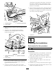
Figure21
1.Solenoidharness3.Connectors,leftandright
2.Valvemanifold
5.Tightenboththeconnectorcenterattachingscrews
securely.
6.Attachthevalvemanifoldsolenoidharness
connectortothematingloaderarmharness
connector(Figure22).
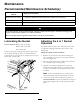
Figure22
1.Valvemanifoldsolenoid
harness
3.Hydraulicconnections
2.Relayharness
7.Atthevalvemanifoldhydraulichoses,positionthe
hoseprotectivesleeveequallydistantaroundthe
uppermostbendinthehose.
8.Locatethesolenoidvalveharnessinthehose
protectivesleevesothatthereissome‘slack’atthe
connectiontotheloaderarmharness.Alsoensure
thatthereissufcient‘loop’intheharnessatthe
connectorstothevalvemanifoldsolenoidsandthe
harnessisnotstrained.
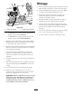
9.Securethehoseprotectivesleeveandsolenoidvalve
harnesstothehydraulichosesusingsuitablecable
ties(Figure23).Tightenthecabletiessecurelyand
cutoffanyexcessstraplengths.
G006242
1
Figure23
1.Cableties
6
FinishingtheInstallation
Partsneededforthisprocedure:
1Dustcap
Procedure
1.Reconnectthebatterytothemachine.Connectthe
negative(black)cableterminaltothenegative(-)
batterypost.Tightentheterminalnutsecurely.
2.Installandclosetherearaccesscover.Refertothe
tractionunitOperator’sManual.
3.Closetheenginehood.Refertothetractionunit
Operator’sManual.
4.Installthekeytothekeyswitchandstarttheengine.
5.Fullyraisetheloaderarm.Disconnectandstorethe
loaderarmcylindersafetylock.
13