
Operator's Manual


G006232
1
2
3
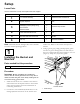
Figure12
1.Relayharness3.Leverbase
2.Plug
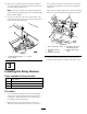
8.Routetheharnessdown,behindthehydrauliclines
andpullitthroughtherewallintheopeningforthe
lower,righthydraulicline(Figure13).
G006233
1
2
4
3
Figure13
1.Relayharness3.Firewall
2.Hydrauliclines
4.Openinginlower,right
hydraulicline
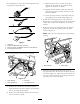
9.Undertheleverarm,reachintotheframeandpull
theharnessup,betweenthetwohardlinesinthe
loaderarm(Figure14).
G006234
1
2
3
Figure14
1.Leverarm3.Hydrauliclines,loaderarm
2.Harness,prongedend
10.Seattheharnessinthearmbyinsertingitupinto
thehollowoftheloaderarmframe.Leaveenough
harnessouttoreachthehydraulicconnectorsonthe
loaderarmfront(Figure15).
G006235
1
2
3
Figure15
1.Loaderarm
3.Lengthofharnesstoreach
hydraulicconnectors.
2.Hollow
11.Locatethelockingconnectorboxwiththefour
holes.Installthefourprongsintothefourholesof
theconnectorasshownanddescribedinFigure16.
Note:Seewiringdiagramformoreinformation.
10