
Operator's Manual


Setup
LooseParts
Usethechartbelowtoverifythatallpartshavebeenshipped.
ProcedureDescription
Qty.
Use
1
4in1bucketassembly1
Installthebucketandmanifold.
2
Nopartsrequired
–
Removetheloaderarm/attachmenttilt
lever.
Relayharness1
Self-tappingscrews(#12[5mm])
2
Boxconnector1
3
Harnessbracket1
Installtherelayharness.
4
Loaderarm/attachmentlever
1
Installtheloaderarm/attachmenttilt
lever.
5
Valvemanifoldsolenoidharness
1
Installthevalvemanifoldsolenoid
harness.
6
Dustcap1Finishtheinstallation.
Note:Determinetheleftandrightsidesofthemachine
fromthenormaloperatingposition.
1
InstallingtheBucketand
Manifold
Partsneededforthisprocedure:
14in1bucketassembly
Procedure
Important:Beforeinstallingtheattachment,
ensurethatthemountplatesarefreeofanydirtor
debrisandthatthepinsrotatefreely.Ifthepinsdo
notrotatefreely,greasethem.
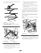
1.Installandsecurethe4in1buckettothetraction
unit’sloaderarmmountplate.Refertothetraction
unit’sOperator’sManualformoreinformationon
connectingattachments.
2.Connectthevalvemanifoldhydraulichosestothe
matinghydraulicconnectorsonthetractionunit
loaderarm.RefertothetractionunitOperator’s
Manual.
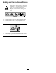
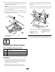
3.Usingagreasegun,pumpgeneralpurposegrease
intothesixgreasettings(threeoneachside)on
the4in1bucketuntilthegreasebeginstooozeout
(Figure3).Wipeawayanyexcessgrease.
G006224
1
Figure3
Leftsideshown
1.Greasettings
6