
Installation Instructions


1
All Rights Reserved
Printed in the USA
2001 by The Toro Company
8111 Lyndale Avenue South
Bloomington, MN 55420-1196
Reel Drive Hose Kit
Reelmaster
6000 Series
Part No. 105-0140
Part No. 105-0139
Form No. 3325-945 Rev A
Installation Instructions
Note: Kit part no. 105–0139 contains components required
for Reelmaster 6500 and 6700. Kit part no. 105–0140
contains components required for only the rear wing cutting
units on Reelmaster 6700 only.
Hydraulic fluid escaping under pressure can
penetrate skin and cause injury.
• Safely relieve all pressure in the hydraulic
system before performing any work on the
hydraulic system.
• Make sure all hydraulic fluid hoses and lines are
in good condition and all hydraulic connections
and fittings are tight before applying pressure to
the hydraulic system.
• Keep your body and hands away from pin hole
leaks or nozzles that eject high pressure
hydraulic fluid.
• Use cardboard or paper to find hydraulic leaks.
• Get immediate medical help if fluid is injected
into skin.
Warning
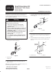
1. Remove and discard all hose guide components
securing hoses to lift arms (Fig. 1).
1
Figure 1
1. Old hose guide
components
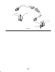
2. Locate and remove hoses to be replaced. Refer to
Figures 5 and 6.
Note: When removing old hoses, remember how they were
routed through components in machine.
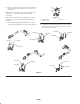
3. Using mounting holes from old hose guides, mount a
new hose guide to each lift arm with (2) screws and
washers (Fig. 2).
1
3
2
Figure 2
1. Hose guide
2. Screw
3. Washer
4. Insert each set of new hoses (3) into a protective sleeve.
Part number of each new hose is shown in Figures 5
and 6.
5. Using the dimensions shown in Figure 3, position and
secure each end of protective sleeve to hoses with a
cable tie.
2
1
1-1/2 in.
(38 mm)
4 in.
(102 mm)
Figure 3
1. Protective cover 2. Cable tie