
Installation Instructions

1
PARTS AND
INSTRUCTION SHEET
FORM NO.106-1248
SPEEDOMETER
FOR USE ON THE MULTI PRO
®
5600 VEHICLE
©The TORO Company - 2002
All Rights Reserved
NOTE: This accessory is intended for use on a MULTI PRO
®
5600 Vehicle equipped with a manual
spray system. For Vehicles equipped with Pro Control Spray Systems, the Speedometer can be
installed to accompany the manual switches, providing a back-up manual system in case of Pro
Control console failure. If the vehicle is equipped with a Pro Control System, it must be
disconnected, and the Control console and hole grommet must be removed prior to installing
the Speedometer.
SET-UP:
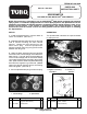
1. Install the Speedometer in vehicle's dash as
shown in illustration. (See FIG.1)
2. Install Speedometer Wire Harness on the right
side of vehicle following the main vehicle
harness. Unplug the main harness from the
wheel motor plug. Connect Speedometer
harness to wheel motor plug using the Three Pin
Weather Pac Plug end.
3. Under the dash, attach the harness' Two Ring
Terminals to the Coolant Gauge on the Multi-Pro
®
5600 vehicle. They will share the threaded post
of the Coolant Gauge with the terminals already
connected; Red Wire Ring terminal to the positive
side. (Stud closest to driver side); Black Wire Ring
terminal to the negative or ground stud. (Middle
stud on the Gauge) Remove and re-use existing
Nuts and tighten. (See FIG. 2)
4. Connect Speedometer plug into harness plug.
OPERATION:
The Speedometer indicates the speed traveled
in miles per hour.
Part No. 106-1247
# Part No. Description Qty
# Part No. Description Qty
1
2
106-1249
22-9-BJD
Wire Harness
Hex Nut, #10 NF
(supplied with Kit)
1
2
3
4
42608
105-3304
Coolant Gauge
(supplied with Vehicle)
Speedometer
FIG. 1
FIG. 2
1. Coolant Gauge 2. Speedometer
1. Negative or Ground (-) 2. Positive (+)
Black Wire Red Wire
2072-5600
Speedo-5600
1
2
2
1
1
1