
Installation Instructions

1
All Rights Reserved
Printed in the USA
2002, 2004 by The Toro Company
8111 Lyndale Avenue South
Bloomington, MN 55420-1196
Scraper Kit
Greensmaster
Flex 21 and DPA Cutting Units
Part No. 106–4661
Part No. 106–4662
Part No. 106–4663
Form No. 3327–886 Rev A
Installation Instructions
1. Loosen screws securing roller shaft to HOC arms
(Fig. 1).
2. Remove plow bolt, washer and flange nut securing one
of the HOC arms to cutting unit sideplate (Fig. 1).
3. Slide HOC arm off roller shaft.
4. Slide roller shaft out of HOC arm on opposite end of
cutting unit.
1
2
4
5
6
3
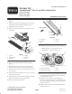
Figure 1
1. HOC arm
2. Adjusting screw
3. Plow bolt
4. Washer
5. Flange nut
6. Screw
5. Slide a scraper hub onto each end of roller shaft
(Fig. 2).
6. Partially thread a set screw into each scraper hub
(Fig. 2). Do not tighten onto roller shaft at this time.
7. Thread a nut, end of scraper and locknut onto each set
screw (Fig. 2).
8. Align scraper hubs and tighten the set screws securing
the hubs to roller shaft.
9. Install the roller and scraper to the cutting unit with the
HOC arm and fasteners previously removed.
10. Center roller between HOC arms.
1
2
5
3
Rear of Roller
4
Figure 2
1. Scraper hub
2. Set screw
3. Nut
4. Scraper
5. Locknut
11. Position the scraper (Fig. 3) on the roller as follows:
• Without groomer – lower rear side of roller
• With groomer – upper rear side of roller
4
3
1
2
Figure 3
1. Scraper (with groomer)
2. Scraper (without groomer)
3. Roller
4. Groomer
12. Rotate scraper to desired operating position, against the
rear side of the roller, and tighten screws securing the
roller shaft to HOC arms.
13. Adjust the nuts on each set screw until there is a
clearance of approximately 1/32 in. (0.8 mm) between
the scraper and the roller. Make sure that the scraper is
parallel to the roller.
14. Adjust to desired height of cut and tighten HOC arm
mounting fasteners.