
Installation Instructions

Formachineswithserialnumbers260000001
andhigher.
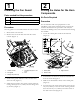
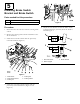
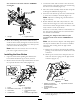
Figure15
1.Taillight2.Pigtailconnector
4.Routetheremainingwireharnessundertheseat,
undertheoorboard,throughthecenterholeinthe
oorboard,nexttothehydraulichosesanduptothe
switchareaunderthedashpanel.
Note:Makesuretheharnessdoesnottouchany
partoftheengineexhaustsystem.
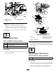
InstallingtheHornButton
1.Openthehornbuttonpackingthatincludesthe
hornswitchandbuttoncap,2screws,andnut.
2.Removethehornbuttoncapandthreadthenutonto
theexposedthreadsoftheswitch(
Figure16).
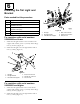
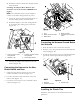
Figure16
1.Screw
5.Hornbutton
2.Wireleadsforhornbutton
6.Lightswitch
3.Hornswitch
7.Connectorfromlight
switch
4.Threadednut
8.Connectortolightswitch
3.Connectthewhiteandredwiresattheendofthe
wiringharnesstothebackofthehornswitchusing
thetwoscrewsincluded(Figure16).
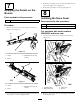
4.Movetheswitchassemblyunderthedashandpush
itthroughthedrilledhole(
Figure16).
5.Screwthehornbuttoncapontotheswitchthreads
tosecuretheassemblytothedash(Figure16).
Note:Adjusttheretainingringandhornbutton
capasnecessary.
6.Reachunderthedashandverifyifthereisawire
leadasshowninFigure16.Thiscomesfromthe
mainharnessunderthelightswitch.Ifthereisawire
lead,connectittothenewharness.
Ifthereisnowirelead,continuetoinstalleitherof
thewireharnessadaptorsthatareassociatedwith
themachineserialnumber.
InstallingtheAdaptorWireHarness(For
machineswithserialnumber240000300and
lower)
Note:Thewireharnessadaptorandclampsplices
areonlyformachinesthatdonothaveitinstalled
underthedashcomingfromthelightswitch
connection.
A.Removetheconnectorfromthelightswitchby
pushingonthetablocatedonthebottomofthe
connector.
B.Matchupthecoloredwiresandsplicethetwo
endsontothewiresgoingintothelightswitch
connector(
Figure17).
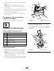
Figure17
1.Adaptorwireharness
splicedtothelightswitch
connectorwires
3.Lightswitchconnector
2.Connectorfromnewwire
harness
C.Connecttheadaptorwireharnesstothenew
harness(Figure17).
9