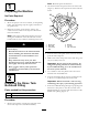
Form No. 3353-529 Rev B Rinse Kit for Multi-Pro® 1200 and 1250 Turf Sprayers Model No. 106-4842 Installation Instructions Note: Determine the left and right sides of the machine from the normal operating position. Safety Safety and Instructional Decals Safety decals and instructions are easily visible to the operator and are located near any area of potential danger. Replace any decal that is damaged or lost. 107-8784 1. From clean water rinse tank 2. From main chemical tank 107-8785 1.
Installation Loose Parts Use the chart below to verify that all parts have been shipped. Procedure 1 2 3 4 5 Description Use Qty.
Note: Retain all parts and fasteners. 1 2. Lift the front tank strap and remove the rinse tank (Figure 1). Remove the cap from the rinse tank and retain. 7 3 2 Preparing the Machine No Parts Required 1 Procedure 1. Move the sprayer onto a level surface, set the parking brake, stop the pump, stop the engine, and remove the ignition key. 2. Drain the contents of the tank to remove any solution in lines. Refer to the Operator’s Manual for more information.
3 Installing the Rinse Nozzle Parts needed for this procedure: 1 2 2 3 3 7 4 6 7 4 5 6 G005789 Figure 2 1. Rinse tank 2. Bulkhead 3. O-ring, clear 4. Plastic nut 5. Retainer fork holes, correct orientation 6. Retainer fork 7. Sump, rinse tank 8. Secure the new bulkhead fitting to the rinse tank using the plastic nut in loose parts as shown in Figure 2. Note: The seal must be seated between the fitting and tank around the entire circumference of the hole edge (Figure 2).
Installing the Rinse Nozzle 3 1 1. Locate the rinse nozzle bulkhead in loose parts. If the bulkhead is shipped assembled, disassemble as shown in Figure 5. 4 A. Remove the plastic ring nut from the bulkhead. B. Push the large, clear O-ring on the bulkhead up flush to the flange fitting to keep it seated. 4 C. Remove the large retainer nut and O-ring 2 G005790 D. Retain all parts. Figure 3 1. Main tank lid 2. Tank ridge, back and right of lid 4 3. Drill point 4. 6.
Important: Do not install the remaining threaded fitting on the end of the rinse tube at this time. 9. Install the 1/2 inch middle fitting into place and secure it with the medium retainer nut from loose parts (Figure 9). 5 6 4 5 1 4 3 3 2 1 2 G005794 G005796 Figure 7 1. Bulkhead assembly 2. Rinse nozzle and tube assembly 3. Main tank surface Figure 9 4. O–ring, small, black 5. Retainer nut, large 4. Retainer nut, medium 5. O-ring, small clear 6. 60 degree elbow 1. Threaded fitting 2.
D. Install the barbed fitting assembly into the open end of the rinse nozzle hose. E. Tighten the hose clamp. 1 13. Set the rinse nozzle hose assembly aside for later installation. 2 4 Installing the Valves G005799 Figure 12 1. Brush Parts needed for this procedure: 1 Decal, 107-8784, rinse tank valve 1 Decal, 107-8785, rinse nozzle valve 1 Rinse tank valve 1 Rinse nozzle valve 2. Reducer 5. Install the bulk reducer fitting to the rinse tank side of the valve (Figure 13).
1 1 4 3 G005801 2 Figure 14 1. Rinse nozzle valve decal, part number 107-8785 2. Rinse nozzle valve, green 3. Flow of valve 3 2 6 3. Brush a non-petroleum based lubricate such as vegetable oil on the bulkhead fitting reducer (Figure 12). 5 4. Install the bulk reducer fitting and O-ring to the rinse tank side of the valve (Figure 13). 1. Rinse tank valve, blue 5. Install the valve onto the lower mixer tee as shown in Figure 13. 2. Rinse nozzle valve, green 3.
5 Installing the Hoses Parts needed for this procedure: 1 Suction hose 1 Rinse tank suction hose 1 Rinse nozzle hose 3 Retainer fork, small 1 Retainer fork, large 3 Plastic tie 11 3 7 8 1 12 4 3 7 2 12 9 10 4 6 4 5 G009154 12 Figure 16 1. Main tank 2. Rinse tank 3. Suction hose 4. Rinse tank suction hose 5. Check valve 6. Correct flow direction 7. Rinse nozzle hose 8. Rinse tank valve 9. Rinse nozzle valve Installing the Suction Hose 10. Boom supply hose, existing 11.
Operation 2. Plumb the hose from the bottom of the rinse tank to the rinse tank valve so that the hose wraps around the pump and is routed along the main pump hose. Rinse Kit Operation 3. Route the rinse tank suction hose behind the valve assembly to the rinse tank side of the rinse tank valve. The operator can use the Rinse Kit to remove residual chemicals from a sprayer tank and affected hoses while the machine is in transit.
Preparing the Machine Note: If the spraying the rinsate is not possible for any reason, drain the main tank contents into a suitable container and dispose of the diluted solution as required by federal, state or local regulations. Position the sprayer on a level surface, set the parking brake, stop the pump, stop the engine, and remove the ignition key. Remove the rinse tank cap and fill the tank with approximately 20 gallons (75 l) with clean water. 11.
Maintenance Inspect Rinse System of Leaks and Damage Service Interval: Before each use or daily—Inspect the hoses for leaks. After the first 5 hours—Inspect hoses for damage. Every 100 hours—Inspect hoses and O-rings for damage After the first 5 hours of operation, inspect all hoses and connections for any leaks or signs of damage. Inspect the hose clamps and retaining forks. Verify that all connections are secure. Replace any damaged parts. Repeat this inspection before each use of the Rinse system.
Troubleshooting Problem No suction of clean water. Unclean tank after rinse. Possible Cause Corrective Action 1. Rinse hose installed incorrectly 1. Verify hose assembly is installed with the flow valve in the correct direction. Reverse if necessary. 2. Rinse valve in wrong position 2. Move valve handle to the rinse tank. 1. Improper introduction of chemicals into the main tank during filling and mixing 1. Ensure the prop agitation while mixing the chemicals. In extreme cases, use a mixing station.
Notes: 14
Notes: 15