
Installation Instructions

1
All Rights Reserved
Printed in the USA
2004 by The Toro Company
8111 Lyndale Avenue South
Bloomington, MN 55420-1196
Hydraulic Control Float Kit
Workman Vehicle w/Serial Numbers 240000001 & Up
Part No. 107–8004
Form No. 3351–668
Installation Instructions
1. Raise the bed.
2. Stop the engine, set the parking brake and remove the
key from the ignition switch.
3. Install the safety support onto the fully extended lift
cylinder rod (if so equipped).
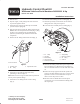
4. Disconnect the hose from the 90 fitting mounted to the
front of the transaxle hydraulic filter head (Fig. 1). Plug
the hose to prevent debris from contaminating the
hydraulic system during the installation of the other
components.
5. Remove the 90 fitting from the filter head (Fig. 1).
1
22
3
Front of vehicle
Figure 1
1. Hydraulic hose
2. 90 fitting
3. Hydraulic filter head
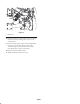
6. Install the new 90 fitting into the filter head,
positioning as shown in figure 2.
Note: Make sure the O–rings are lubricated and positioned
correctly in the hydraulic fittings.
7. Install the new tee fitting into the new 90 fitting
(Fig. 2).
8. Install the barbed fitting into the tee fitting (Fig. 2).
9. Install the previously removed hose onto the barbed
fitting. The hose clamp is not required.
10. Connect the hose assembly to the tee fitting (Fig. 2).
1
2
3
4
5
6
7
8
9
Figure 2
1. 90 Fitting
2. Tee fitting
3. Barbed fitting
4. Hose assembly
5. Female quick coupler
6. Straight fitting
7. Male quick coupler
8. 90 Fitting
9. Cable tie
11. Install the 90 fitting and the male quick coupler to the
hose assembly (Fig. 2). Route the hose assembly over
the rear frame tube and secure it to the tube with a cable
tie.
12. Remove the safety support from the lift cylinder rod
and lower the bed. With the engine off, cycle the remote
hydraulics control lever back and forth a couple of
times to release the pressure to lines.
13. Disconnect the two bed lift hoses from the quick
couplers (Fig. 3). Cover the bed lift hose fittings with
the coupler caps.