
Installation Instructions

1
All Rights Reserved
Printed in the USA
2003 by The Toro Company
8111 Lyndale Avenue South
Bloomington, MN 55420-1196
Drum Rebuild Kit
Greensmaster
Flex 21
Part No. 107–9025
Form No. 3351–298
Installation Instructions
Note: On machines with serial numbers prior to
210009999, the Drum Cover Update Kit, Part No.
107–9026 must be also be installed on the machine.
Obtain the kit from your Authorized Toro Distributor.
Note: If the Transport Kit, Part No. 105–9900 has been
installed the Drum Cover Update Kit is not required.
1. Position the machine on a clean, level surface.
Remove transport wheels, if so equipped.
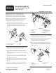
2. Remove the capscrew, washer, spacer and nut securing
the traction drive belt covers to each side of the
machine (Fig. 1) . Retain the fasteners, covers and
spacers.
1
2
3
4
Figure 1
1. Traction drive belt cover
2. Capscrew & washer
3. Spacer
4. Nut
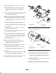
3. Release the belt tension and remove the traction drive
belts from the sides of the machine (Fig. 2).
4. Remove the locknut (18mm socket), large washer,
small pulley and woodruff key from each end of the
differential shafts (Fig. 2). Retain the keys, washers
and locknuts.
5. Loosen the set screws securing the flange bearing
locking collars to each end of the differential shafts
(Fig. 2). Loosen the collars.
6. Remove the capscrews, washers and nuts securing the
bearing flangettes and the bearings to the side plates
(Fig. 2).
7. Remove the flangettes, bearings and locking collars.
Retain the bearing flangettes and fasteners (Fig. 2).
2
3
4
1
8
7
5
7
5
6
Figure 2
1. Traction drive belt
2. Locknut
3. Large washer
4. Small pulley
5. Woodruff key
6. Bearing locking collar
7. Bearing flangette
8. Bearing
8. Remove the fasteners securing the engine mounting
straps to the frame. Retain the fasteners.
9. Slide the engine/gearbox assembly towards the left
side of the machine until the right end of the
differential shaft clears the sideplate.
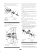
10. Place a flangette, a new extended race bearing (set
screw end away from the engine/gearbox) and another
flangette onto the end of the left differential shaft as
shown in figure 3.
1
2
3
4
5
4
Figure 3
1. Locknut
2. Large washer
3. Small pulley
4. Bearing flangette
5. Bearing