
Installation Instructions


2
1
2
3
4
5
6
7
8
9
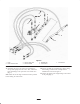
To Valves
To Hydraulic Fluid Reservoir
Figure 4
1. Pump
2. Hoses to valve (2)
3. 90_ fitting (2)
4. Straight fitting (2)
5. Adapter
6. Straight fitting
7. Elbow fitting (2)
8. Suction hoses to manifold
tube (2)
9. Manifold tube
15. Assembly and connect the new hoses and fittings to
the top of the pump and to the valve (Fig. 4).
Note: Make sure all O–rings are lubricated and in position
before making the connections.
16. Loosely assembly the straight fitting, adapter fitting,
elbow fittings, suction hoses w/clamps and the
manifold tube as shown in figure 4.
17. Connect the adapter and straight fitting to the bottom
of the pump (Fig. 4).
18. Connect the hose from the hydraulic fluid reservoir to
the new manifold tube with a new hose clamp.
19. Tighten all clamps, hoses and fittings.
20. Mount the woodruff key, pulley and pulley bushing to
the pump shaft with the capscrews and washers
previously removed (Fig. 3).
21. Insert the belt onto the pump pulley (Fig. 2 & 3).
22. Position a large wrench on the tensioner. Rotate the
tensioner clockwise until the decal is aligned with 15_
on tensioner tube.
23. Insert capscrew into aligned guide holes and secure
with nut. If holes are not exactly aligned, rotate guide
to the next higher hole until aligned.
24. Tighten capscrew, on back side of frame, to lock
tensioner.
25. Install the drive shield to the impeller housing with the
capscrews, washers, and nuts.