
Installation Instructions


3
The following instructions are to be used on the
Goossen Model VV 20000.
1. Park the machine on a clean flat surface, lower all
attachments, shut the tractor engine off and remove the
key from the ignition.
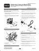
2. Remove the capscrews, washers and nuts securing the
drive shield to the impeller housing (Fig. 5). Remove
the shield.
1
Figure 5
1. Drive shield
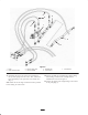
3. On back side of frame, loosen the capscrew securing
the belt tensioner to the frame (Fig. 6).
1
2
3
4
4
5
Figure 6
1. Tensioner guide
2. Capscrew & nut
3. Capscrew (back of frame)
4. Pump pulley
5. Belt
4. Position a large wrench on the tensioner. Rotate the
tensioner clockwise to release the tension on the
capscrew and nut securing the tensioner guide to the
drive mount (Fig. 6).
5. Remove the capscrew and nut securing the tensioner
guide to the drive mount (Fig. 6). The belt tension will
be released when the capscrew is removed.
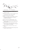
6. Remove the belt from the pump pulley (Fig. 6 & 7).
7. Remove the capscrews and washers securing the
pulley bushing and pulley to the pump shaft. Remove
the pulley bushing, woodruff key and the pulley from
the pump shaft (Fig. 7).
1
2
3
4
Figure 7
1. Pulley bushing
2. Pulley
3. Woodruff key
4. Pump
8. Place a drain pan under the pump.
9. Disconnect the two hoses and fittings from the top of
the pump (Fig. 8).
10. Disconnect and remove the hose and fitting from the
single spool valve (Fig. 8).
11. Disconnect and remove the hose and fitting from the
control valve (Fig. 8).
12. Disconnect the hose and fitting from the manifold
(Fig. 8). Do not disconnect the other end of the hose.
13. Disconnect the hose, fittings from the bottom of the
pump (Fig. 8).
14. Loosen the hose clamp and separate the suction hose
from the manifold (Fig. 8). Remove all loose
components. Retain the hose clamps and manifold for
re–use.
15. Remove the capscrews, washers and nuts securing the
pump to the frame (Fig. 7).
16. Install the new pump to the frame using the capscrews,
washers and nuts previously removed (Fig. 7).