
Installation Instructions
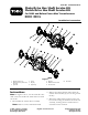
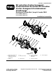

4. Apply a light coat of oil to the hex por tion of
the hex shaft.
5. Slide the r ubber friction wheel and hex
tr unnion assembly onto the hex shaft, ensuring
that the r ubber friction wheel is oriented on
the side closest to the k eyw a y (c hain-dri v e
model only).
6. Assemble the roll pins on the hex shaft with
the hex tr unnion assembly betw een them.
Note: T he roll pins should be centered on
the hex shaft.
7. Place the square k ey in the k eyw a y on the hex
shaft.
8. Assemble the sproc k et onto the hex shaft and
o v er the k ey .
Note: T he sproc k et should be flush ag ainst
the hex shaft shoulder and the k ey should not
protr ude bey ond the sproc k et.
9. Tighten the sproc k et to the hex shaft and
k eyw a y using the set screws pro vided. T or que
the screws to 60 to 80 in-lb .
10. R e peat ste ps 7 through 9 for the other end of
the hex shaft (clutc h-dri v e model only).
11. Assemble the spacer onto the sproc k et end of
the hex shaft (c hain-dri v e model only).
12. Inser t one of the bearing retainers through the
hole in the sno wthro w er frame and secure it to
the frame using the screws that y ou previously
remo v ed.
13. Inser t the end of the hex shaft assembly into
the bearing retainer so that the hex tr unnion is
on the right side of the r ubber friction wheel
( Figure 1 ).
14. Inser t the other bearing retainer through the
hole in the other side of the sno wthro w er
frame and capture the other end of the hex
shaft assembly with the bearing retainer .
15. Secure the bearing retainer to the sno wthro w er
frame using the screws that y ou previously
remo v ed.
16. Attac h the c hains and g rease the components .
17. Assemble the remaining traction dri v e
components .
Note: R efer to the ser vice man ual.
2