
Installation Instructions

1
All Rights Reserved
Printed in the USA
W 2005 by The Toro Company
8111 Lyndale Avenue South
Bloomington, MN 55420-1196
Latch Kit for No. 6 and No. 7 Mowers
Groundsmaster
)
4700–D
Part No. 110–0450
Form No. 3353–413 Rev. A
Installation Instructions
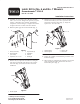
1. Assemble the L.H. latch to the L.H. latch assembly
with a 1/2 x 2–1/4 in. flange head capscrew, (2) nylon
washers, a flatwasher and a locknut. Assemble the
components as shown in figure 1. Tighten the locknut
enough so the latch can move but resists motion.
2. Bond the plastic grip onto the latch handle (Fig. 1).
1
2
3
4
4
6
5
4
7
Figure 1
1. Latch (L.H. shown)
2. Latch assembly
(L.H. shown)
3. Capscrew, 1/2 x 2–1/4 in.
4. Nylon washer (2)
5. Flatwasher
6. Locknut
7. Plastic grip
3. Remove the (2) capscrews and washers securing the
front of the #6 (left) lift arm support to the traction
unit frame (Fig. 2). Retain the washers for the kit
installation.
1
Figure 2
1. Lift arm support
4. Mount the L.H. latch assembly to the lift arm support
and the frame with (2) 5/8 x 2 in. capscrews and
previously removed washers (Fig. 3). Torque the
capscrews to 155–160 ft–lbs.
1
2
4
3
Figure 3
1. Latch assembly
2. Lift arm support
3. Lift arm (#6)
4. Lift arm rod
5. Repeat the assembly and installation procedures on the
#7 lift arm (right).
6. When storing or transporting the machine, raise the lift
arms and pivot the latches onto the lift arm rods to
latch them in place (Fig. 3).