
Installation Instructions

Form No. 3355-348 Rev A
Speed Limiter Kit
For Sand Pro® 3040 and 5040 Traction Unit
Model No. 110–1371
Installation Instructions
Note: Deter mine the left and right sides of the mac hine from the nor mal operating position.
Step
1
Installing the Speed Limiter
Parts needed for this step:
1
Bolt (5/16 x 1-1/4 inches)
1
Bolt (5/16 x 5 inches)
1
Jam nut (5/16 inch)
1
Speed limit lever assembly
1
Spacer
1
Wave washer
1
Flat washer (5/16 inch)
1
Traction pedal stop
1
Spring bracket
1
Spring
1
Spring adjustment pin
Procedure
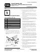
1. R emo v e the n ut, spacer , w a v e w asher , flat
w asher and bolt securing the traction pedal to
the pi v ot tube under the floor plate ( Figure 1 ).
R etain both w ashers for use in the installation
of the kit.
G003738
345621
Figure 1
1. Traction pedal assembly 4. Flat washer
2. Pivot tube 5. Wave washer
3. Bolt
6. Spacer
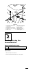
2. T hread the jam n ut (5/16 inc h) half w a y onto
the speed limiter bolt (5/16 x 1-1/4 inc hes)
( Figure 2 ).
3. T hread the speed limiter bolt (5/16 x 1-1/4
inc hes) into the top of the tab on the speed
limiter lev er ( Figure 2 ). Do not tighten the jam
n ut at this time .
4. Inser t the new long er bolt (5/16 x 5 inc hes)
through the hole in the traction pedal ( Figure
2 ). T he bolt is to be inser ted from the left side
of the traction pedal.
5. Inser t the new spacer and speed limit lev er
onto the bolt as sho wn in Figure 2 .
6. Secure the speed limiter assembly and the
traction pedal to the pi v ot with the previously
remo v ed w a v e w asher , flat w asher (5/16
inc h) and new loc k n ut ( Figure 2 ). Do not
o v er tighten the n ut as the components m ust
pi v ot freely .
7. R emo v e the n ut, securing the traction pedal
stop bolt to the underside of the floor plate
( Figure 2 ). Do not c hang e the height of the
pedal stop .
8. Inser t the spring brac k et onto the stop bolt
and the spring brac k et tab into the hole in the
floor plate ( Figure 2 ). Secure the spring brac k et
to the bolt with the n ut previously remo v ed.
9. Hook the extension spring to the speed limiter
assembly tab and to the adjustment pin ( Figure
2 ).
10. Inser t the spring adjustment pin through the
hole in the spring brac k et and secure with a
loc k n ut ( Figure 2 ).
11. Adjust the speed limiter bolt to attain the
desired amount of pedal tra v el and tighten the
jam n ut ( Figure 2 ).
12. Tighten or loosen the spring adjustment pin
n ut to attain the desired amount of force on
the speed limiter ( Figure 2 ).
© 2006—The Toro® Company
8111 Lyndale Avenue South
Bloomington, MN 55420
Register at www.Toro.com. Original Instructions (EN)
Printed in the USA.
All Rights Reserved