
Operator's Manual


Setup
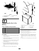
LooseParts
Usethechartbelowtoverifythatallpartshavebeenshipped.
ProcedureDescription
Qty.
Use
Fanassembly1
U-bolt2
Locknut(3/8inch)
4
1
U-boltplate2
Installthefanassembly.
Fuseholder1
Ringterminal2
Spliceconnector
1
Fuse,20amp1
2
Cableties
4
Installthefantothebattery.
Note:Determinetheleftandrightsidesofthemachinefromthenormaloperatingposition.
1
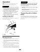
InstallingtheFanAssembly
Partsneededforthisprocedure:
1Fanassembly
2U-bolt
4
Locknut(3/8inch)
2U-boltplate
Procedure
1.DisengagethePTOandsettheparkingbrake.
2.Stoptheengine,removethekey,andwaitforall
movingpartstostopbeforeleavingtheoperating
position.
3.Removetheplastictieholdingtheswitchtothefan
screen.
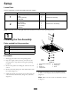
4.Removetheknob,angenutandsmallwasherfrom
theswitch(
Figure2).
5.Installtheswitchpostintothescreenandsecurethe
switchwiththesmallwasher,angenut,andknob
(
Figure2).
Figure2
1.Fanandframeassembly5.Smallwasher
2.Switch
6.Flangenut
3.Switchnut
7.Knob
4.Largewasher
6.InstallthefanframeontopoftheROPSwith2
U-bolts,2U-boltplates,and2locknuts(3/8inch)
(Figure3).
Note:MakesuretheU-boltsareinstalledasshown
in
Figure3.
4