
Operator's Manual

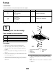
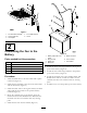
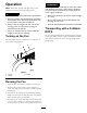
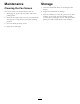


Figure3
1.Fanandframeassembly4.2inchROPSframe
2.Locknut(3/8inch)
5.U-bolt
3.U-boltplate
2
ConnectingtheFantothe
Battery
Partsneededforthisprocedure:
1Fuseholder
2Ringterminal
1
Spliceconnector
1Fuse,20amp
4
Cableties
Procedure
1.Installtheblackwiretothefuseholderwithasplice
connector(
Figure4).
2.Installtheringterminaltotheendofthefuseholder
andthewhitewire(
Figure4).
3.Installthewhitewiretothenegativebatteryterminal
andinstallthefuseholdertothepositivebattery
terminal(Figure4).
4.Routetheelectricalwiretothebatteryalongthe
machineframeandtheROPSframe.Makesurethe
electricalwiredoesnotinterferewithanymoving
parts.
5.Installthefuseintothefuseholder(Figure4).
Figure4
1.Batterywithboltsinthe
posts
5.Spliceconnector
2.Ringterminal6.Fuse,20amp
3.Whitewire7.Fuseholder
4.Blackwire
6.Installthewhitewireringterminaltothenegative
postonthebattery(Figure4).
7.Installthefuseholderringterminaltothepositive
postonthebattery(
Figure4).
8.Installtheelectricalwiretothemachineframeand
ROPSframewiththe4cableties.Makesurethe
electricalwiredoesnotinterferewithanymoving
parts.
9.Installthebootoverthepositivepostonthebattery.
5