
Installation Instructions

1
All Rights Reserved
Printed in the USA
W 2007 by The Toro Company
8111 Lyndale Avenue South
Bloomington, MN 55420-1196
Front Brush Kit for Full Roller
Front Brush Kit for Narrow Roller
Front Brush Kit for Wide Roller
Greensmaster
)
DPA Cutting Units
Part No. 110–3963
Part No. 110–3964
Part No. 110–3965
Part No. 110–2354
Part No. 110–2355
Part No. 110–2353
Form No. 3357–757 Rev A
Installation Instructions
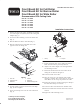
1. Remove the plow bolt, washer and flange nut securing
one of the height of cut (HOC) arms to the cutting unit
sideplate (Fig. 1).
2. Loosen the roller mounting screws in the HOC arms
(Fig. 1).
3. Slide the HOC arm off the roller shaft (Fig. 1).
4. Slide the roller shaft out of the HOC arm on the
opposite end of the cutting unit.
1
2
4
5
6
3
Figure 1
1. HOC arm
2. Adjusting screw
3. Plow bolt
4. Washer
5. Flange nut
6. Roller mounting screw
5. Loosely install a capscrew and nut onto each clamp
(Fig. 2). Do not tighten.
6. Insert a shaft clamp onto each end of the roller shaft
(Fig. 2).
1
2
Figure 2
1. Clamp 2. Scraper
7. Loosely install the roller to the cutting unit with the
HOC arm and fasteners previously removed.
8. Adjust to the desired height of cut and tighten HOC
arm mounting fasteners.
9. Position the brush between the front roller and the
cutting unit as shown in the figure 2.
10. Center the brush on the roller.
11. Move the scraper in or out until the desired roller
clearance is attained. The scraper must not contact the
roller. Make sure the scraper is parallel to the roller.
12. Tighten the capscrews and nuts securing the clamps to
the roller shaft. Torque to 96 in–lbs.
13. Center the roller and brush between the HOC arms.
14. Rotate the brush down until the desired turf contact is
attained.
15. Tighten the roller mounting screws.