
Installation Instructions

1
All Rights Reserved
Printed in the USA
W 2005 by The Toro Company
8111 Lyndale Avenue South
Bloomington, MN 55420-1196
Accessory Wiring Kit
Groundsmaster
)
4000–D & 4100–D
Part No. 110–3263
Form No. 3353–730 Rev A
Installation Instructions
1. Position the machine on a level surface, lower the
cutting unit, stop the engine, engage the parking brake
and remove the key from the ignition.
2. Disconnect the negative battery cable from the battery.
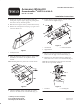
3. Remove the control panel cover (Fig. 1) to gain access
to the fuse block area.
Figure 1
1. Control panel cover
4. Using the dimensions shown in figure 2, locate, mark
and drill (2) .50” holes in the top of the control
console.
Note: Mounting holes may exist in the control console.
Figure 2
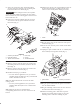
5. Clean the mounting surface and apply the control
decal over the holes on the control console (Fig. 3).
6. Loosely mount a toggle switch in each hole with the
washers and nuts supplied (Fig. 3).
1
2
3
Figure 3
1. Console decal
2. Toggle switches
3. Harness connectors
7. Plug the (2) connectors from the accessory wire
harness onto the toggle switch terminals (Fig. 3).
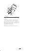
8. Mount the new fuse block below the existing fuse
block with a #10 x 3/4 in. screw and locknut (Fig. 4).
Note: Do not install the new fuse block if a third fuse
block has been previously installed.
1
2
Figure 4
1. Fuse block 2. Grounding bolt