
Installation Instructions
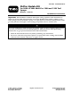

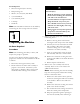

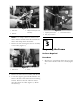
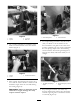
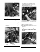
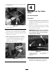


Figure 18
1. New selector frame 3. Bolt and lock washer
2. Frame
4. Line up position
3. Use tw o bolts (5/16 x 1 inc h) and tw o loc k
n uts (5/16 inc h) to secure the brac k et to the
frame ( Figure 18 ). T or que the fasteners to 9
ft-lb (13 N ⋅ m)
4. Install the shift selector to the brac k et using
tw o bolts (5/16 x 2-1/2 inc h), 1 shim, tw o
spacers , tw o w ashers and tw o loc k n uts (5/16
inc h) ( Figure 19 ).
Figure 19
1. Selector bracket 5. Shim
2. Selector assembly
6. Spacer
3. Bolt 7. Lock nut
4. Washer
5. T or que the bolts to 16 ft-lb (22 N ⋅ m).
6. R oute the loc k out cable along the frame ,
behind the operator’ s position, with the existing
wiring . Do not secure the cable at this time .
7. R oute the cable through the 3/4 inc h hole
previously drilled in the floor frame ( Figure
20 ).
Figure 20
1. 3/4 inch drilled hole 4. Lock out cable
2. Frame
5. Speed limiter linkage
3. Opening in the frame
10