
Installation Instructions


8. R oute cable thr ough the speed limiter linkag e
if the mac hine is equipped ( Figure 20 ).
9. F eed the cable out from under the frame ,
to w ard the front of the v ehicle , under the floor
board, via the opening in frame ( Figure 20 ).
10. R oute the cable to the front of the mac hine
along the frame , under the floor board, and
begin to steer it bac k to w ard the brak e pedal
and linkag e assembly .
11. Prop the brak e pedal b y placing a bloc k behind
the pedal ar m on the floor board.
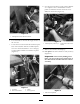
12. R emo v e the cotter and clevis pin securing the
master cylinder linkag e to the brak e pedal ar m
( Figure 21 ).
Figure 21
1. Brake pedal arm
4. Cotter pin
2. Brake master cylinder
linkage
5. Location for bracket
mounting.
3. Clevis pin
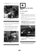
13. If a brak e switc h exists it can be remo v ed no w
as follo ws:
A. R emo v e the fasteners securing the switc h
to the brac k et w elded to the brak e pedal
ar m.
B . Disconnect the connector betw een the
brak e switc h and the wiring har ness .
C . Discard the switc h
D . Tie bac k the wiring and connector on
the main wiring har ness . Use a plastic tie
to secure it to the frame , a w a y from the
mo ving components of pedal assemblies .
14. Mount the loc k out cable brac k et to the frame
at the w eld n ut using the existing bolt. Hand
tighten the fastener to allo w for adjustment
( Figure 22 ).
15. Slide the r ubber co wl on the loc k out
cable to w ard the ring linkag e to expose the
adjustment n uts ( Figure 22 ).
Figure 22
1. Frame
5. Adjustment nut
2. Bracket 6. Rubber cowl
3. Bolt 7. Ring linkage
4. Lock out cable
16. Loosen the adjustment n uts on the loc k out
cable to se parate them and slip the cable into
the brac k et g roo v e ( Figure 22 ).
17. Secure the cable , master brak e cylinder linkag e
and brak e pedal ar m with the long er clevis pin
(3/8 x 1-1/8 inc h) and cotter pin pro vided.
Bend the cotter pin ends outw ard to secure the
linkag e ( Figure 23 ).
11