
Installation Instructions
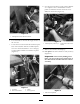
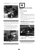


Figure 23
1. Brake pedal arm 5. Adjustment nut, seated
around bracket
2. Master cylinder linkage 6. Ring linkage
3. Bracket
7. Clevis pin (3/8 x 1-1/8 inch)
4. Cable
8. Cotter pin, new
18. Mo v e the loc k out cable adjustment n uts so
that slac k in the cable betw een the brak e pedal
pin and the brac k et is remo v ed. Tighten the
adjustment n uts to seat the cable in the brac k et
( Figure 23 ).
19. Tighten the fastener to secure the brac k et in
place . T he bloc k behind the brak e pedal can
no w be remo v ed.
20. Secure the routed cable loop to the front of the
frame at existing w eld n uts in the frame using
tw o R-clamps and bolt ( Figure 24 ).
Figure 24
1. Cable 3. Accelerator pedal arm
2. R-clamp 4. Brake pedal arm
Important: Do not allo w the ca ble to
kink or f old when securing it to the frame.
21. Install the larg e g rommet at the outer windo w
in the frame . Cut the g rommet and install it to
the sides and bottom of the cut out protecting
the cable from areas of the frame it is most
lik ely to w ear ag ainst ( Figure 25 ).
Figure 25
1. Cable
3. Large grommet
2. Rubber sleeve
22. Install r ubber sleev e to the v er tical face of the
frame the cable is routed around. Star t the
sleev e at the bottom and slide upw ard into
place ( Figure 25 ).
23. Cut the 3/4 inc h g rommet as necessar y and
install it into the hole drilled in the frame .
24. Use plastic ties to secure the loc k out cable to
the frame , behind the operator’ s position, with
the existing wiring har ness .
Step
6
Installing the Belt Kit (Part
Second Kit)
No Parts Required
Procedure
At this time it recommended to complete the Belt
Kit installation if necessar y .
12