
Installation Instructions


4. Secure the cable linkag es to the new shift
selector using the existing clevis and cotter
pins .
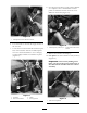
5. Install the shift selector cables using all existing
fasteners and clamps to the new brac k et
( Figure 27 ).
Figure 27
1. Shift cable arms, in line
with selector
4. Clamps, existing
2. Cable fasteners, existing
5. Existing adapter plate (not
on all machines)
3. Shift cable
Step
9
Adjusting the Lock Out
Cable
No Parts Required
Procedure
T he new shift selector position ma y require the
adjustment of the selector cables and the loc k out
cable . Use the follo wing procedures test and adjust
the cables .
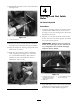
1. With the shift selector installed, stand o v er the
assembly and apply light force (appro ximately
5 lbs) on shift lev er to w ard the right side of
the v ehicle ( Figure 28 ).
Figure 28
2. T he solenoid pin should be just flush with the
outer face of the selector linkag e it rests in. If
not, adjust as follo ws:
A. Use the swi v el fitting adjuster to set
solenoid pin de pth flush with the shift
selector brac k et surface sho wn in Figure 29 .
Note: If necessar y , remo v e the engine air
filter co v er to access the cable adjustment
n uts .
Figure 29
1. Shift selector bracket
4. Jam nut
2. Solenoid pin 5. Solenoid
3. Adjustment tting
14