
Installation Instructions


B . After the de pth is set release force on shift
lev er . Loc k adjustment into place with the
jam n ut.
3. T est the loc k out cable . V erify the pin is fully
retracted with the brak e is pressed.
Step
10
Adjust the Shift Selector
Cables.
No Parts Required
Procedure
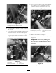
1. At the transaxle , remo v e cotter pins and clevis
pins that secure cable clevis to shift lev ers
( Figure 30 ).
Figure 30
1. Shift cable jam nut 4. Shift cable 1/reverse
2. Clevis pin
5. Shift cable (2/3)
3. Clevis Jam nut
2. Chec k that the threads of the shift cables are
centered in the mounting brac k ets . If needed,
readjust shift cable jam n uts .
3. Adjust cable clevis with clevis jam n uts so that
forw ard and bac kw ard free pla y of clevis is
equal relati v e to the hole in the transaxle shift
lev er . Tighten clevis jam n uts .
4. Secure cable clevis to shift lev ers with clevis
pins and cotter pins .
5. Chec k shift lev er for proper operation.
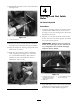
Step
11
Finishing the Installation
No Parts Required
Procedure
1. R e place the components remo v ed:
A. Spra y tank saddles and assembly
B . F enders and Seat
2. R efer to the Ser vice Manual and P ar ts Catalo g for
additional infor mation.
15