
Installation Instructions


T ools R equir ed
• Sheet metal guard (10 x 24 inc h)
• R eciprocating sa w
• Metal 1/8–3/16 (inc h) 18T Blade
• 3/4 inc h Drill bit
• 5/16 T ransfer punc h
• C-clamps
• Hand file
Note: T he installation of this kit can be aided b y
referencing the P ar ts Catalo g and Ser vice Manual .
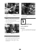
Step
1
Preparing the Machine
No Parts Required
Procedure
Note: T he follo wing procedure , at times , will
require tw o people to perfor m.
Use the Ser vice Manual and P ar ts Catalo g to help
pre pare the mac hine for the installation of this kit
as follo ws:
1. Disconnect the neg ati v e batter y cable .
2. Drain and rinse the main tank assembly to
pre pare it for remo v al. Flush the system
thoroughly to eliminate direct contact with
c hemicals while w orking on the mac hine .
Chemicals ar e hazardous and can cause
per sonal injur y .
• R ead the dir ections on the chemical
la bels bef or e handling the chemicals
and f ollo w all man uf actur er
r ecommendations and pr ecautions.
• K eep chemicals a w ay fr om y our
skin. Should contact occur , w ash the
af fected ar ea thor oughl y with soap
and clean w ater .
• W ear go g g les and an y other pr otecti v e
equipment r ecommended by the
chemical man uf actur er .
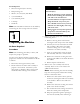
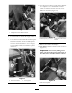
3. R emo v e the main spra y tank assembly and
connecting hoses:
A. R emo v e the long bolts and fasteners
securing the tank straps to the tank saddles .
B . In v entor y the hoses attac hed to the main
tank assembly . Disconnect and label
eac h hose taking care to note routing
orientations for future assembly .
C . Using an o v erhead lift, secure the main
tank assembly and raise it off the frame .
D . R emo v e the fasteners securing the front
and rear tank saddles to the frame . R emo v e
the saddles .
E. R etain all par ts and fasteners .
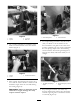
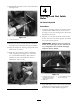
4. R emo v e the seat assembly and console
assembly . R efer to the Ser vice Manual for
additional infor mation.
Note: W hen remo ving the console assembly ,
k ee p the control panels and electrical wiring
har ness connections intact.
A. R emo v e the shift selector knob , jam n ut
and screws securing the shift boot assembly
to the fenders . R emo v e the shift boot
assembly .
B . R emo v e the fasteners securing the control
panel to the fender assembly .
C . Do not disconnect the wiring connections
from the control panel components .
D . Drop the panel through the openings in
the console assembly when remo ving it.
3