
Installation Instructions


E. Lift seat base from mac hine .
5. R etain all par ts and fasteners for later
installation.
Step
2
Removing the Splash Guard
and Selector Assembly
No Parts Required
Procedure
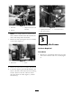
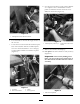
1. Locate the metal splash guard to the left of the
operating position.
2. R emo v e the 4 bolts retaining the splash guard
and brac k et to the frame and existing shift
selector assembly ( Figure 1 ). T here are tw o
shor t bolts in the front and tw o long er bolts to
the rear securing the brac k et and guard. R etain
the brac k et and fasteners for later use .
Figure 1
1. Splash guard 3. Short bolts
2. Bracket 4. Long bolts
3. Pi v ot the entire splash guard and console
assemble forw ard, around the operating
position so that it is out of the w a y , on the
floorboard.
4. T he left console wiring har ness bundle has
leads connected to the engine and another
connected to the shift solenoid. Detac h and
label these leads at the connectors .
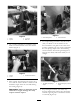
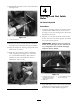
5. At the shift selector , remo v e clevis and cotter
pins securing the shift cable linkag e ( Figure 2 ).
K ee p the clevis and cotter pins in the cable
linkag es .
Figure 2
1. Shift selector 3. Clevis and cotter pin
2. Shift cable linkage
6. R emo v e the bolts securing the shift cables and
clamps to the mac hine and mo v e the shift cable
assembly rearw ard, out of the w a y ( Figure 3 ).
R etain all fasteners and clamps .
4