
Installation Instructions


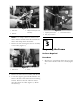
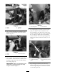
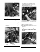
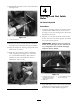


Figure 3
1. Shift cables
3. Adapter bracket (not on all
machines)
2. Fasteners
Note: If an adapter brac k et is betw een the
cables and the mac hine frame disassemble the
cables and clamps from the brac k et.
7. R emo v e the bolt securing the selector assembly
to the frame ( Figure 4 ).
Figure 4
1. Shift selector
2. Frame
8. R emo v e the shift selector assembly and discard.
9. Locate the neg ati v e g round cable bolted to the
frame at the base of the shift selector mounting
brac k et. R emo v e the bolt and loc k w asher
then disconnect the cable ( Figure 5 ). R etain
all fastener(s).
Figure 5
1. Negative ground cable 3. Shift selector bracket
2. Bolt, ring lock washer
Step
3
Preparing the Frame
No Parts Required
Procedure
1. Measure 3-1/4 inc h do wn from the top of the
shift selector brac k et and score a mark ( Figure
6 ).
5