
Installation Instructions
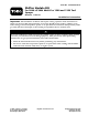

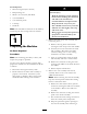

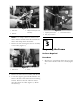

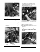
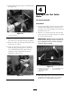


Figure 6
1. Frame
3. 3-1/4 inch
2. Square
4. Mark here
2. Use a square and scribe to extend the score
mark to a horizontal line across the selector
brac k et ( Figure 7 ).
Figure 7
1. Square
3. Scored horizontal line
2. Scribe
3. Place a metal sheet betw een the engine v alv e
co v er and the selector brac k et. T he sheet will
shield the engine from the sa w blade during
the cutting ( Figure 8 ).
Important: F ailur e to shield the engine
will r esult in engine dama ge that may
r equir e extensi v e r epair s.
Figure 8
1. Sheet metal guard 2. Selector bracket
4. Use reciprocating sa w with a new , fine tooth
(18T) sa w blade to cut the brac k et at the
line . Extend the sa w guide to the outer most
position. Hold the sa w at an angle to minimize
the sa ws plung e de pth and to a v oid making
contact with the sheet metal guard ( Figure 9 ).
Grip the sa w fir mly and hold it steady to cut
straight.
Figure 9
1. 18T blade, full plunge
depth
2. Reciprocating saw, held at
angle.
5. Stop cutting the brac k et 3/4 of the w a y
through and finish b y cutting into the brac k et
from the opposing side . Cut until the brac k et
is remo v ed ( Figure 10 ).
6