
Installation Instructions


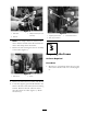
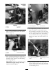
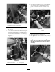
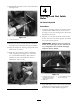


Figure 10
1. Cutting from the other direction to nish
6. Use a hand file to smooth all rough surfaces at
the cut area.
7. Locate the new selector brac k et and line up the
base of the brac k et with the rounded square
cut out in the frame brac k et. Use a clamp(s)
to temporarily hold the new brac k et in place
( Figure 11 ).
Figure 11
1. Cut frame 3. Clamp
2. New selector bracket
4. Line up position
8. Use the tw o lo w er holes on the selector brac k et
as a template and a .320 diameter transfer
punc h to mark the location for holes to be
drilled on the frame ( Figure 12 ).
Figure 12
1. Transfer punch (.320 inch)
2. Lower holes in the selector
bracket
9. R emo v e the brac k et and clamp(s).
10. Drill pilot holes at the marks to v erify accuracy
( Figure 13 ).
Important: Inaccuratel y drilling these
holes can pr ev ent the pr oper placement of
the shift selector brack et and new selector
assembl y .
Figure 13
1. Pilot hole being drilled.
7