
Installation Instructions

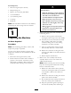

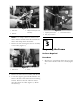
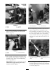
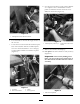
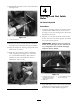


Figure 17
1. Pilot hole being drilled 3. 3/4 inch Bit
2. Brake reservoir
4. R emo v e any bur rs around the hole and clean
the entire area of all metal sha vings and debris .
5. Pre p the surfaces b y cleaning all exposed metal
with acetate or acetone .
6. P aint all exposed metal surfaces with blac k
touc h-up spra y paint. Allo w to dr y .
Step
5
Mounting the Shift Selector
Assembly
Parts needed for this step:
1
Selector mounting bracket
2
Bolt (5/16 x 1 inch)
2
Lock nut, serrate ange(5/16 inch)
1
Shift selector assembly
2
Bolt (5/16 x 2-1/2 inch)
2 Spacer
2
Flat washer
2
Lock nut, nylon (5/16 inch)
1
Clevis pin (3/8 x 1-1/8 inch)
1
Cotter pin
2
R-clamp
1
Rubber grommet (1-1/2 inch)
1
Rubber grommet (3/4 inch)
1
Rubber sleeve
Procedure
1. R emo v e the metal shield protecting the engine
and install the neg ati v e g round cable remo v ed
previously using the existing fasteners ( Figure
5 ).
2. Install the new shift selector mounting
brac k et to the frame at the location previously
pre pared. Align the holes in the brac k et
with the previously drilled holes in the frame
( Figure 18 ). T he rounded square cutout in the
frame should be flush with the selector brac k et
indent.
9