
Installation Instructions
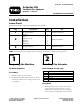


Figure 1
Right side shown
1. Clevis
3. Jam nut
2. Adjustment nut 4. Center boom
2. Install the boom actuators as sho wn in Figure
2 , using 2 clevis pins and 2 cotter pins . Bend
the ends of the cotter pins to secure them.
Figure 2
Right side shown
1. Actuator
3. Cotter pin
2. Clevis pin 4. Center boom
3. Connect the actuator po w er plug to the open
connector on the existing wire har ness .
Step
3
Adjusting the Actuator
No Parts Required
Procedure
T o ensure trouble-free operation, do not allo w the
extension boom str ucture to contact any other
por tion of the boom str ucture during operation.
Y ou m ust allo w the actuator to tra v el its full strok e
and be stopped b y its o wn inter nal limits .
W hen the boom is fully upright, ensure that the
ball suppor t str ucture on the boom does not
contact the center boom cut out. T here should be
a g ap equal to the thic kness of a 12-g aug e piece
of steel (0.106 inc h or 3 mm) betw een these tw o
components ( Figure 3 ).
Figure 3
1. Actuator extended 3. Cutout, center boom
2. 12-gauge piece of steel
(0.106 inch or 3 mm)
4. Extension boom, upright
T o ensure this g ap , adjust the boom as follo ws:
1. Set the boom in the horizontal position.
2. Adjust the adjustment n ut close to the clevis
possible ( Figure 4 ).
2