
Installation Instructions
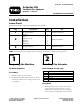


Figure 4
1. Adjustment nut
3. Actuator
2. Clevis
4. Jam nut
3. Secure the clevis into position b y tightening
the jam n ut ag ainst the center boom brac k et.
4. Eng ag e the electric lift to raise the boom to the
full, upright position.
Note: T he actuator m ust be fully extended
at this point (at the end of its tra v el, a clutc h
will diseng ag e and y ou will hear clic king if the
po w er is held on to the actuator).
5. Inser t a strip of 12-g aug e steel stoc k betw een
the ball suppor t and the cutout on the center
boom ( Figure 3 ).
6. Loosen the jam n ut and rotate the adjustment
n ut to bring the ball suppor t into contact with
the 12-g aug e sheet stoc k shim and the cutout
on the center boom.
7. Tighten the adjustment n ut.
8. R emo v e the 12-g aug e steel stoc k shim.
9. Mo v e the boom throughout its length of tra v el
to ensure that no par t of the boom assembly
contacts any objects that ma y impede the
boom tra v el.
Note: W hen y ou complete the adjustment,
ensure that the axis of the clevis pin is
horizontal.
3