
Installation Instructions

1
All Rights Reserved
Printed in the USA
W 2007 by The Toro Company
8111 Lyndale Avenue South
Bloomington, MN 55420-1196
Attachment Frame Kit
For Groundsmaster 3320/3280–D
Part No. 110–8540
Form No. 3356–589 Rev. A
Installation Instructions
Remove the Cutting Unit from
the Lift Arms
1. Position the machine on level surface, lower the
cutting unit to the floor, move the lift lever to the Float
position, shut the engine off, and engage the parking
brake.
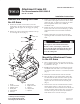
2. Remove the capscrew and washer mounted to the top
of each height of cut rod (Fig. 1).
1
2
3
4
5
67
10
11
9
8
Figure 1
1. Lift arm
2. Castor arm bracket
3. Height of cut rod
4. Lift arm pads
5. Thrust washers
6. Clevis pin
7. Hair pin cotter
8. Height of cut collar
9. Clevis pin
10. Hair pin cotter
11. Capscrew
3. Remove the hairpin and clevis pin securing the height
of cut collar to the height of cut rod on the rear of the
cutting unit (Fig. 1). Remove the height of cut collar.
These components will be used to install the
attachment frame.
4. Remove the hair pin cotters and clevis pins securing
the lift arms to the castor arm brackets (Fig. 1). These
components will be used to install the attachment
frame.
5. Roll the cutting unit away from the traction unit,
separating the male and female sections of the PTO
shaft .
Danger
If the engine is started and the PTO shaft is
allowed to rotate, serious injury could result.
Do not start the engine and engage the PTO lever
when the PTO shaft is not connected to the gear
box on the cutting unit.
Mount the Attachment Frame
to the Lift Arms
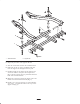
1. Insert a support rod into each end of the rear tube on
the attachment frame (Fig. 2). Make sure the thru hole
is positioned at the top.
2. Loosely attach the bottom of each support rod to the
attachment frame tube with a 1/2 x 1 inch capscrew,
1/2 inch lock washer and 9/16 x 1–3/8 inch flat washer
(Fig. 2).
3. Position the attachment frame under the lift arms.
4. Move the lift lever to the Float position. Push a lift
arm down until the holes in the lift arm line up with
the holes in the attachment frame brackets and the
support rods can be inserted into the lift arm pads
(Fig. 2).
5. Secure the lift arm to the attachment frame brackets
with (2) thrust washers, a clevis pin and a hair pin
cotter. Position the thrust washers between the lift arm
and the attachment frame brackets (Fig. 2). Insert the
end of the cotter pin into the slot in the attachment
frame bracket tab to retain the cotter pin.