
Installation Instructions
1
All Rights Reserved
Printed in the USA
W 2006 by The Toro Company
8111 Lyndale Avenue South
Bloomington, MN 55420-1196
Variable Orifice Kit
Sand/Infield Pro 3040 and 5040 Traction Unit
Part No. 112–1433
Form No. 3355–321 Rev A
Installation Instructions
1. Position the machine on a level surface, lower the
attachment, stop the engine, engage the parking brake,
and remove key from ignition switch.
2. Place a drain pan under the rear lift cylinder.
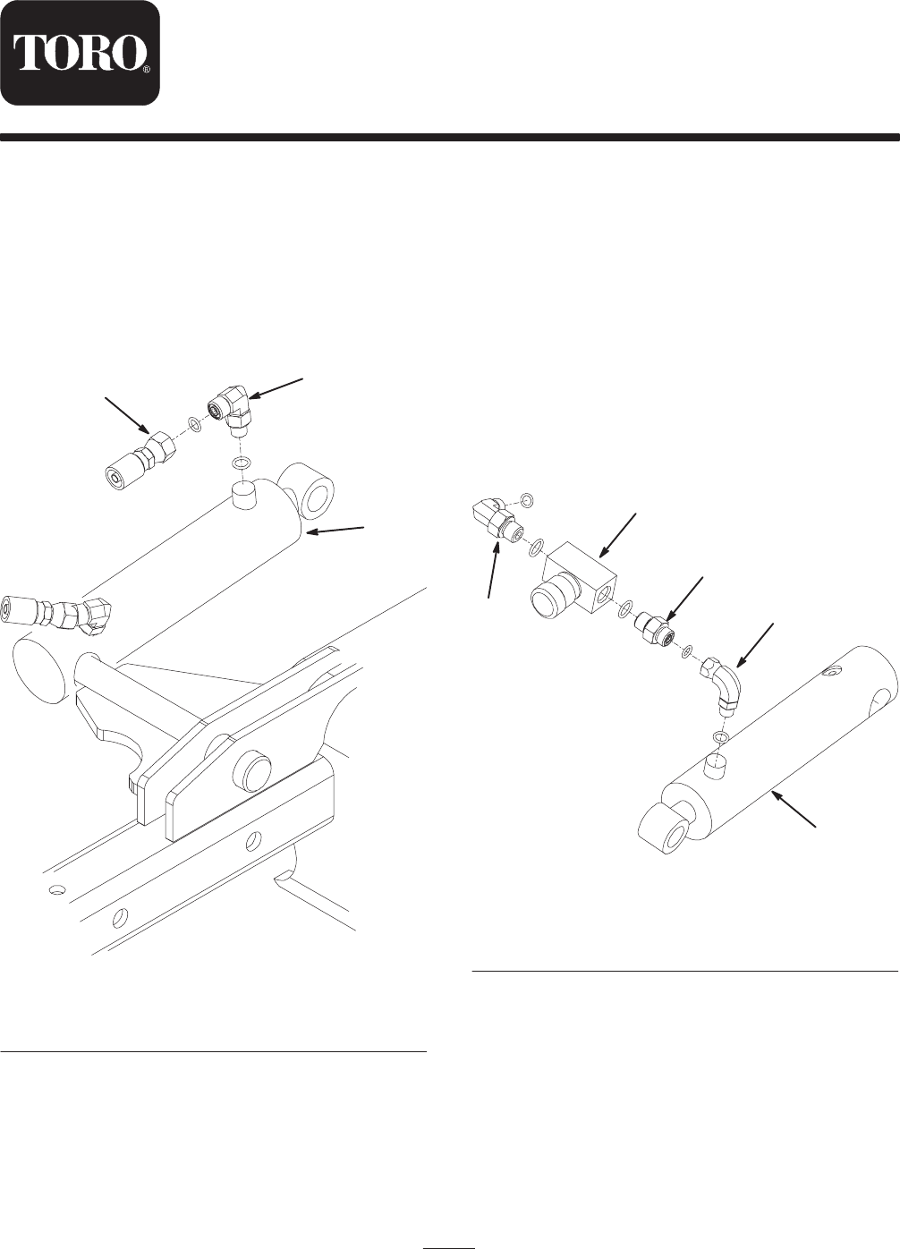
3. Clean around the hydraulic fitting secured to the rod
end of the lift cylinder (Fig. 1).
4. Disconnect the hydraulic hose from the fitting and
remove the fitting from the cylinder (Fig. 1).
1
2
3
Figure 1
1. Lift cylinder
2. Fitting
3. Hydraulic hose
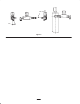
5. Loosely install the O–ring boss end of the swivel nut
90 degree fitting into the lift cylinder (Fig. 2). Do not
tighten the jam nut at this time.
Note: Position the fitting as shown in figure 3.
6. Install the straight adapter fitting to the needle valve
(Fig. 2).
Note: Make sure the O–rings are lubricated and in
position before installing the components.
7. Install the 90 degree adapter fitting into the needle
valve (Fig. 2).
8. Install the needle valve adapter fitting to the swivel nut
90 degree fitting on the lift cylinder (Fig. 2).
9. Connect the hydraulic hose to the 90 degree adapter
fitting (Fig. 2).
Note: Before all the connections are tightened, make sure
the orifice kit is not interfered with during the cylinder
operation.
1
2
4
5
3
Figure 2
1. LIft cylinder
2. Swivel nut 90 degree
fitting
3. 90 degree adapter fitting
4. Straight adapter fitting
5. Needle valve
10. Check the hydraulic fluid level and replenish as
required. Do not over-fill. Refer to Operator’s Manual
for hydraulic fluid specifications.
11. Rotate the needle valve clock wise to decrease the rate
at which the attachment is lowered. Rotate the valve
counter–clockwise to increase the rate at which the
attachment is lowered. The valve is infinitely
adjustable.