
Installation Instructions


5. R emo v e the blade from the spindle . Sa v e the
blade .
6. R emo v e the bolts holding the spindle to the
mo w er dec k. Sa v e the n uts and bolts ( Figure 1 ).
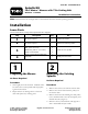
Figure 1
1. Bolt and washer 6. Spindle assembly
2. Pulley
7. Bolt (save)
3. Nut and washer
8. Spacer
4. Aluminum hub 9. Spindle shaft
5. Locknut (save)
Step
3
Installing the New Spindle
Parts needed for this step:
1
Spindle assembly
3
Bolt, (3/8 x 3/4 inch)
1
Blade bolt, (5/8 x 2–1/4 inches)
3
Small curved washer
1
Large curved washer (blade bolt)
Procedure
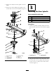
1. Install the spindle assembly under the mo w er
dec k with the previously remo v ed bolts ( Figure
2 ).
Figure 2
1. Locknut (existing)
3. Spindle assembly
2. Mower deck
4. Bolt (existing)
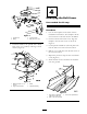
2. Align the three holes in the dec k pulley with
the three holes in the spindle hub and install
3 bolts (3/8 x 3/4 inc h) and 3 small cur v ed
w ashers ( Figure 3 ).
2