
Installation Instructions
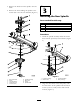
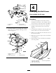

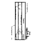


Figure 3
1. Spindle hub 3. Curved washer
2. Pulley
4. Bolt (3/8 x 3/4 inch)
3. Install the blade to the spindle with a blade
bolt (5/8 x 2–1/4 inc hes) and larg e cur v ed
w asher ( Figure 4 ).
Figure 4
1. Blade bolt (5/8 x 2–1/4
inches)
3. Blade
2. Large curved washer 4. Spindle assembly
Step
4
Modifying the Belt Covers
Parts needed for this step:
1
Template
Procedure
1. Cut out the template in the bac k of these
installation instr uctions . T he template will be
used to locate a hole that needs to be drilled.
2. On the bottom of the belt co v er , align the
template onto the belt co v er as sho wn in
Figure 5 .
3. Center punc h and drill an 3/8 inc h pilot hole
into the belt co v er at the cor rect location.
4. Drill an 1–1/8 inc h hole into the belt co v er at
the cor rect location.
5. R e peat the previous ste ps for the second belt
co v er ( Figure 5 ).
6. Install the belt co v ers and lo w er the mac hine
onto the g round.
Figure 5
1. Align holes in template
with holes in belt cover
3. Belt cover upside down
2. Drill 1–1/8 inch hole here
3