
Installation Instructions

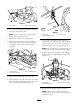
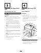
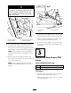


Figure 1
1. Belt guide nut 2. Engine pulley belt guide
2. Use a 1/4-inc h soc k et and ratc het to remo v e
the engine pulley belt guide .
Note: Note in whic h hole the belt guide
mounts for re-installation later .
3. R emo v e the belt from the engine pulley .
4. R emo v e and discard the cotter pin and flat
w asher that secure the loop end of the dec k
eng ag ement cable to the lo w er PTO lev er
( Figure 2 ).
Figure 2
1. Lower PTO lever 3. Deck engagement cable
2. Loop end of the cable
5. Slip the cable end off the PTO lev er stud.
6. F rom the right side of the unit, locate the other
end of the dec k eng ag ement cable on the cross
brace at the bac k of the dec k ( Figure 3 ).
Figure 3
1. Hairpin clip 3. Cross brace slot
2. Deck engagement cable
7. At the cable end, remo v e the hair pin clip ,
pull bac k on the cable housing until the metal
por tion of the cable is in the cross brace slot,
and lift the cable out of the slot ( Figure 3 ).
Note: T he straight leg of the hair pin clip g oes
through a hole in the fitting end of the cable .
8. Unhook the dec k eng ag ement cable spring
from the right hand idler brac k et on the dec k
( Figure 4 ).
Figure 4
1. Engine pulley 3. Right hand idler bracket
2. Left hand belt cover
9. R emo v e the dec k from under the tractor .
Note: R efer to the Operator’ s Manual for
instr uctions on ho w to remo v e the dec k from
under the tractor .
2