
Installation Instructions


W atch that the fuel line connected to the
fuel tank is not kink ed, pulled fr om the
fuel tank nipple, and that ther e is not
str ess placed on the nipple that w ould
cause it to br eak.
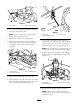
Figure 6
1. Steering column 3. Stop engagement bracket
2. Flange locknuts 4. Bottom of fuel tank
5. Use a 1/2-inc h soc k et and ratc het to remo v e
and discard the 2 flang e loc kn uts that secure
the connection of the stop eng ag ement brac k et
and the upper and lo w er PTO lev ers ( Figure 6 ).
Note: T he 2 car riag e screws are secured in
the upper PTO lev er b y 2 speed n uts; do not
remo v e .
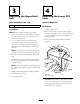
6. R emo v e the stop eng ag ement brac k et and
lo w er PTO lev er from the tw o screws attac hed
to the upper PTO lev er .
Note: If the spring attac hed to the lo w er
PTO becomes detac hed, install it as sho wn in
Figure 7 .
Figure 7
1. Shoulder bolt 3. Lower PTO lever
2. Spring
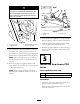
7. Push up the lo w er PTO lev er to slip the split
plastic bushing out the hex hole in the frame .
8. Push the plastic split bushing off the round
section of the lo w er PTO lev er shaft.
9. R emo v e the lo w er PTO lev er do wn through
the hex hole of the frame . Discard the lo w er
PTO lev er .
Step
5
Install the New Lower PTO
Lever
Parts needed for this step:
1
Lower PTO lever
2
Flange locknut
Procedure
1. Install the new lo w er PTO lev er , using the 2
flang e loc kn uts pro vided in the kit.
R efer to Figure 8 and Figure 9 for the cor rect
assembly sequence .
4